1
GATE ECE 2018
Numerical
+1
-0
A traffic signal cycles from GREEN to YELLOW, YELLOW to RED and RED to GREEN.
In each cycle, GREEN is turned on for 70 seconds, YELLOW is turned on for
5 seconds and the RED is turned on for 75 seconds. This traffic light has to be implemented
using a finite state machine (FSM). The only input to this FSM is a clock of 5 second period.
The minimum number of flip-flops required to implement this FSM is _______.
Your input ____
2
GATE ECE 2017 Set 1
Numerical
+1
-0
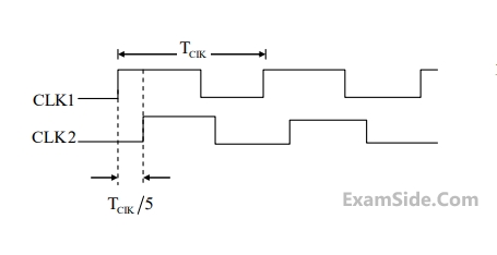
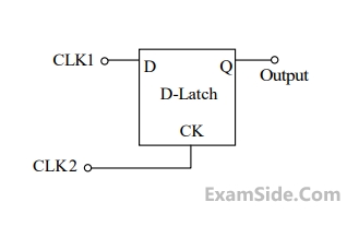
Consider the D-Latch shown in the figure, which is transparent when its clock input CK is high and has zero propagation delay. In the figure, the clock signal CLK1 has a 50% duty cycle and CLK2 is a one-fifth period delayed version of CLK1. The duty cycle at the output latch in percentage is ___________.
Your input ____
3
GATE ECE 2017 Set 1
MCQ (Single Correct Answer)
+1
-0.3
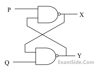
In the latch circuit shown, the NAND gates have non-zero, but unequal propagation delays. The present input condition is: P = Q = "0‟. If the input condition is changed simultaneously to P = Q = "1", the outputs X and Y are
4
GATE ECE 2016 Set 2
Numerical
+1
-0
Assume that all the digital gates in the circuit shown in the figure are ideal, the resistor 𝑅 = 10 𝑘Ω and the supply voltage is 5 𝑉. The D flip-flops D1, D2, D3, D4 and D5 are initialized with logic
values 0, 1, 0,1 and 0, respectively. The clock has a 30% duty cycle.
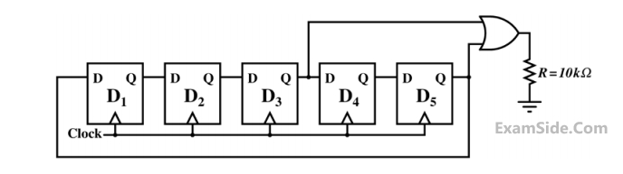
The average power dissipated (in mW) in resistor R is ______.
Your input ____
GATE ECE Subjects
Browse all chapters by subject
General Aptitude
Network Theory
Microprocessors
Signals and Systems
Discrete Fourier Transform and Fast Fourier Transform Discrete Time Signal Fourier Series Fourier Transform Continuous Time Signal Laplace Transform Fourier Transform Representation of Continuous Time Signal Fourier Series Transmission of Signal Through Continuous Time LTI Systems Miscellaneous Sampling Continuous Time Linear Invariant System Discrete Time Linear Time Invariant Systems Discrete Time Signal Z Transform Transmission of Signal Through Discrete Time Lti Systems
Electromagnetics
Digital Circuits
Electronic Devices and VLSI
Control Systems
Communications
Engineering Mathematics