Diodes · Analog Circuits · GATE ECE
Marks 1
In the circuit shown, the n : 1 step-down transformer and the diodes are ideal. The diodes have no voltage drop in forward biased condition. If the input voltage (in Volts) is $V_s(t) = 10 \sin\omega t$ and the average value of load voltage $V_L(t)$ (in Volts) is $\frac{2.5}{\pi}$, the value of n is _____.

An asymmetrical periodic pulse train $v_{\text {in }}$ of 10 V amplitude with on-time $T_{\mathrm{ON}}=1 \mu \mathrm{~s}$ is applied to the circuit shown in the figure. The diode $D_1$ is ideal.
 The difference between the maximum voltage and minimum voltage of the output waveform $v_0$ (in integer) is $\_\_\_\_$ V.

 The magnitude of the current i2 (in mA) is equal to __________.


(1) less expensive transformer
(2) smaller size transformer, and
(3) suitability for higher voltage application.
Of these,Marks 2
Consider the ideal diodes D1 and D2 as shown in the Figure with cut-in voltage $V_\gamma=$ 0 Volt and $v_i(t)$ is in Volt.
The maximum voltage (Volt) of the output $v_o(t)$ is $\_\_\_\_$ .
(rounded off to two decimal places)

All the diodes in the circuit given below are ideal.
Which of the following plots is/are correct when $V_I$ (in Volts) is swept from $-M$ to $M$ ?

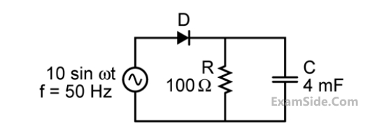
The diode in the circuit shown below is ideal. The input voltage (in Volts) is given by $V_1=10 \sin 100 \pi t$, where time $t$ is in seconds.
The time duration (in ms, rounded off to two decimal places) for which the diode is forward biased during one period of the input is ________.

In the circuit shown below, D$$_1$$ and D$$_2$$ are silicon diodes with cut-in voltage of 0.7 V. $$\mathrm{V_{IN}}$$ and $$\mathrm{V_{OUT}}$$ are input and output voltages in volts. The transfer characteristic is

A circuit and the characteristics of the diode (D) in it are shown. The ratio of the minimum to the maximum small signal voltage gain $${{\partial {V_{out}}} \over {\partial {V_{in}}}}$$ is __________ (rounded off to two decimal places).


The value of the ripple u (in volts) is ______________.

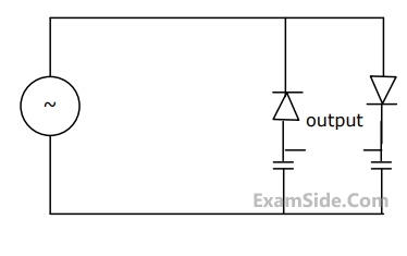
 The bias current IDC through the diodes is
The ac output voltage vac is
The bias current IDC through the diodes is
The ac output voltage vac is