Pin Details of 8085 and Interfacing with 8085 · Microprocessors · GATE ECE
Marks 1
1
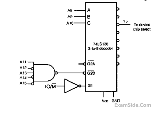
In the circuit shown, the device connected to Y5 can have address in the range


GATE ECE 2010
2
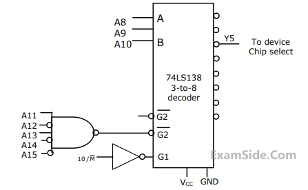
In the circuit shown, the device connected to Y5 can have address in the range


GATE ECE 2010
3
In the 8085 microprocessor, the RST6 instruction transfers the program
execution to the following location
GATE ECE 2000
4
The number of hardware interrupts (which require an external signal to interrupt)
present in an 8085 microprocessor are
GATE ECE 2000
5
If $$CS\;=\overline{A_{15}}\;A_{14}\;A_{13}$$ is used as the chip select logic of a 4K RAM in an 8085
system, then its memory range will be
GATE ECE 1999
6
An I/O processor control the flow of information between
GATE ECE 1998
7
In an 8085$$\mu$$P system, the RST instruction will cause an interrupt
GATE ECE 1997
8
The decoding circuit shown below has been used to generate the active low chip select signal for a microprocessor peripheral. (The address lines are designated as $${A_0}$$ to $${A_7}$$ for I-O address)


GATE ECE 1997
9
In a microprocessor, when a CPU is interrupted, it
GATE ECE 1995
10
In a microcomputer, wait states are used to
GATE ECE 1993
11
In an 8085 microprocessor system with memory mapped I/O,
GATE ECE 1992
12
A 8bit $$\mu $$p has 16bit address bus. A 1KB memory chip is interfaced to processor as shown ib figure. The address range for the chip is _____________.


GATE ECE 1988
13
A microprocessor with a 16-bit address bus is used in a linear memory selection configuration (i.e. Address bus lines are directly used as chip selects of memory chips) with 4 memory chips. The maximum addressable memory space is
GATE ECE 1988
14
For a microprocessor system using I/O-mapped I/O the following statement(s) is NOT true
GATE ECE 1988
Marks 2
1
An 8 Kbyte ROM with an active low Chip Select input CS is to be used in an 8085
microprocessor based system. The ROM should occupy the address range 1000H to 2FFFH.
Theaddress lines are designated as A15 to A0, where A15is the most significant address
bit.Which one of the following logicexpressions will generate the correct $$\overline{CS}$$ signal for this
ROM?
GATE ECE 2016 Set 2
2
For the 8085 microprocessor, the interfacing circuit to input 8-bit digital data (DI0 – DI7)
from an external device is shown in the figure. The instruction for correct data transfer is


GATE ECE 2014 Set 2
3
There are four chips each of 1024 bytes connected to a 16 bit address bus as
shown in the figure below. RAMs 1,2,3 and 4 respectively are mapped to
addresses


GATE ECE 2013
4
An I/O peripheral device shown in figure (b) below is to be interfaced to an 8085
microprocessor. To select the I/O device in the I/O address range D4H – D7H,
its chip-select (CS) should be connected to the output of the decoder shown in
figure (a) below:


GATE ECE 2006
5
What memory address range is NOT represented by chip 1 and chip 2 in
figure? A0 to A15 in this figure are the address lines and CS means Chip Select.


GATE ECE 2005
6
The 8255 Programmable Peripheral Interface is used as described below.
I. An A/D converter is interfaced to a microprocessor through an 8255. the conversion is initiated by a signal from the 8255 on Port C. A signal on Port C causes data to be strobed into Port A.
II. Two computers exchange data using a pair of 8255s. Port A works as a bidirectional data port supported by appropriate handshaking signals.
The appropriate modes of operation of the 8255 for I and II would beGATE ECE 2004
7
An 8085 microprocessor based system uses a 4K × 8-bit RAM whose starting
address is AA00H. The address of the last byte in this RAM is
GATE ECE 2001