Transient Response · Network Theory · GATE ECE
Marks 1
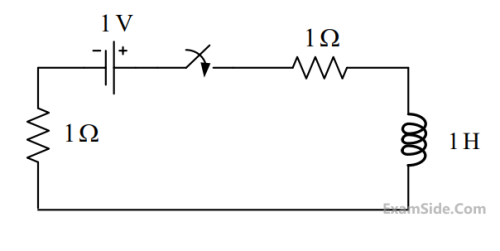
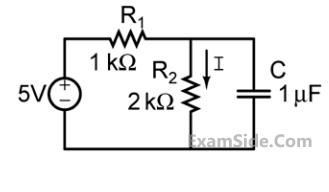
In the circuit given below, the switch $S$ was kept open for a sufficiently long time and is closed at time $t = 0$. The time constant (in seconds) of the circuit for $t > 0$ is _______ .

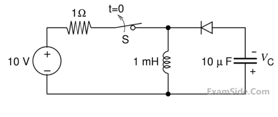
As shown in the circuit, the initial voltage across the capacitor is 10 V, with the switch being open. The switch is then closed at $t = 0$. The total energy dissipated in the ideal Zener diode $(V_Z = 5 { V})$ after the switch is closed (in mJ, rounded off to three decimal places) is _________.

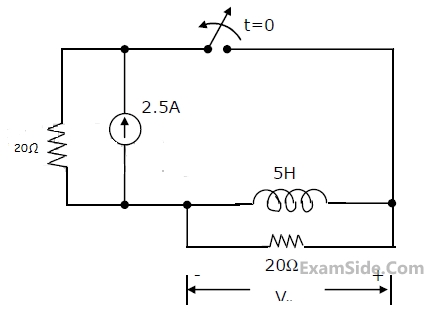
In the circuit shown below, switch S was closed for a long time. If the switch is opened at t = 0, the maximum magnitude of the voltage $$\mathrm{V_R}$$, in volts, is __________ (rounded off to the nearest integer).

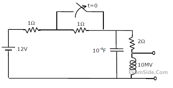
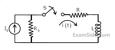
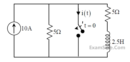
The circuit in the figure contains a current source driving a load having an inductor and a resistor in series, with a shunt capacitor across the load. The ammeter is assumed to have zero resistance. The switch is closed at time $t=0$.
 Initially, when the switch is open, the capacitor is discharged, and the ammeter reads zero ampere. After the switch is closed, the ammeter reading keeps fluctuating for some time till it settles to a final steady value. The maximum ammeter reading that one will observe after the switch is closed (rounded off to two decimal places) is $\_\_\_\_$ A.
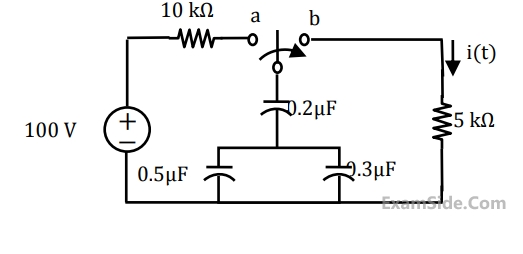
The switch in the circuit in the figure is in position $P$ for a long time and then moved to position $Q$ at time $t=0$

The value of $\frac{d v(t)}{d t}$ at $t=0^{+}$is
 If time t is in seconds, the capacitor voltage VC (in volts) for t>0 is given by
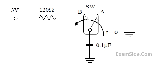
For the circuit shown below different time constants are given :

1. $0.5 \times 10^{-3} \mathrm{sec}$
2. $2 \times 10^{-3} \mathrm{sec}$
3. $0.25 \times 10^{-3} \mathrm{sec}$
4. $10^{-3} \mathrm{sec}$
What are the charging and discharging times respectively :
Marks 2
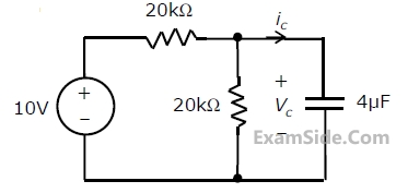
The switch S$$_1$$ was closed and S$$_2$$ was open for a long time. At t = 0, switch S$$_1$$ is opened and S$$_2$$ is closed, simultaneously. The value of i$$_\mathrm{c}$$(0$$^+$$), in amperes, is

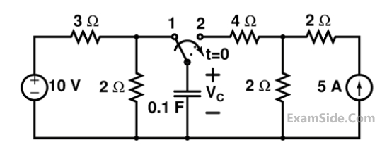
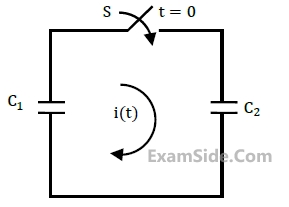
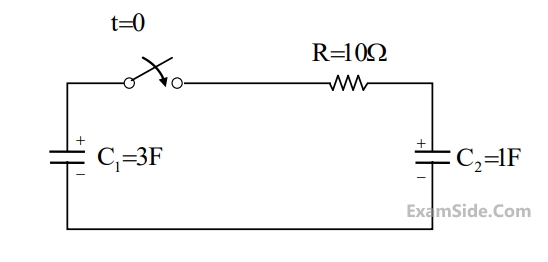
In the circuit shown in the figure, the switch is closed at time $t=0$, while the capacitor is initially charges to -5 V (i.e., $\left(\theta_C(0)=-5 \mathrm{~V}\right)$.
 The time after which the voltage across the capacitor becomes zero (rounded off to three decimal places) is $\_\_\_\_$ ms .
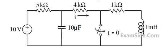
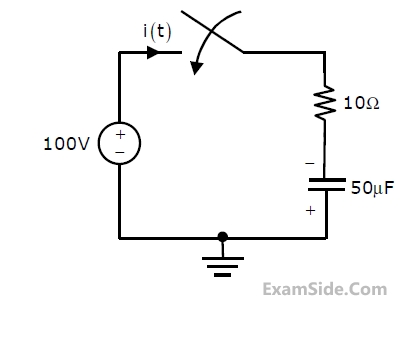
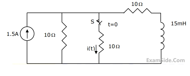
The switch in the circuit, shown in the figure, was open for a long time and is closed at t = 0. The current i(t) (in ampere) at t = 0.5 seconds is ________
 The steady state magnitude of the capacitor voltage VC (in volts) is ____________.
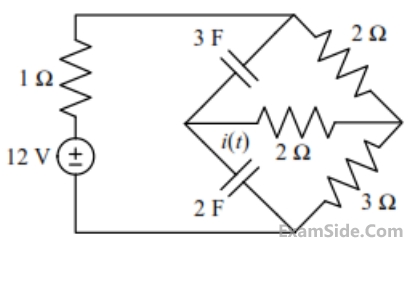
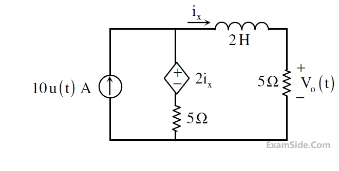
In the circuit shown in the figure, the value of V0(t) (in Volts) for $$t\rightarrow\infty$$ is ______.
In the circuit shown below, the initial charge on the capacitor is 2.5 mC, with the voltage polarity as indicated. The switch is closed at time t=0. The current i(t) at a time t after the switch is closed is
 For t > 0, the voltage across the resistor is
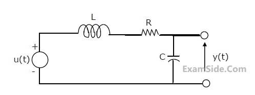
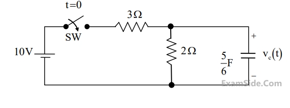
For t > 0, the output voltage Vc(t) is
For t > 0, the voltage across the resistor is
For t > 0, the output voltage Vc(t) isThe circuit shown in the figure is used to charge the capacitor C alternately from two current sources as indicated. The switches S1 and S2 are mechanically coupled and connected as follows
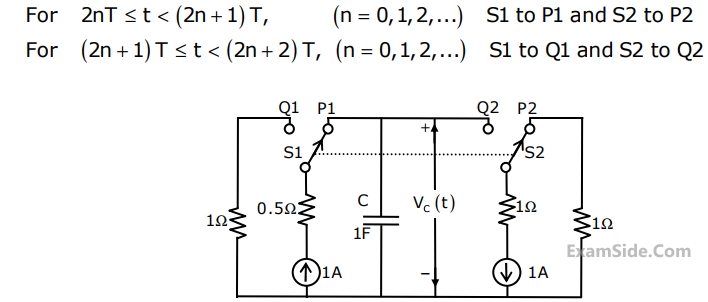
Assume that the capacitor has zero initial charge. Given that u(t) is a unit step function, the voltage Vc(t) across the capacitor is given by
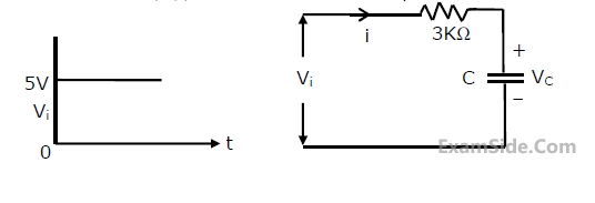
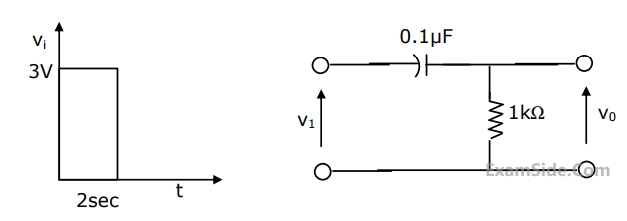
A square pulse of 3 volts amplitude is applied to C-R circuit shown in figure. The capacitor is initially uncharged. The output voltage v0 at time t=2 sec is
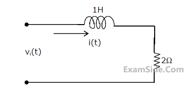
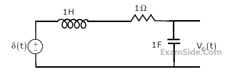
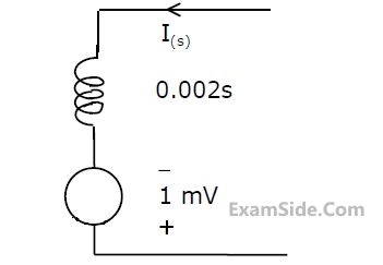
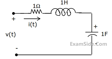
The circuit shown in Fig, has initial current $${\mathrm i}_\mathrm L\left(0^-\right)\;=\;1\;\mathrm A$$ through the inductor and an initial voltage $${\mathrm v}_\mathrm C\left(0^-\right)\;=\;-1\;\mathrm V$$ across the capacitor. For input v(t) = u(t), the Laplace transform of the current i(t) for t ≥ 0 is
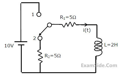
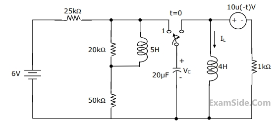
The circuit is given in figure.Assume that the switch S is in position 1 for a long time and thrown to position 2 at t = 0.
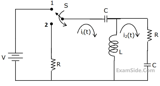
I1(s) and I2(s) are the Laplace transforms of i1(t) and i2(t) respectively. The equations for the loop currents I1(s) and I2(s) for the circuit shown in figure, after the switch is brought from position 1 to position 2 at t = 0, are
The circuit is given in figure.Assume that the switch S is in position 1 for a long time and thrown to position 2 at t = 0.
At t = 0+, the current i1 is
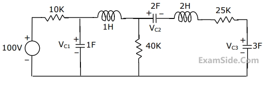
The voltage VC1, VC2 and VC3 across the capacitors in the circuit in Fig., under steady state, are respectively
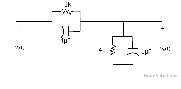
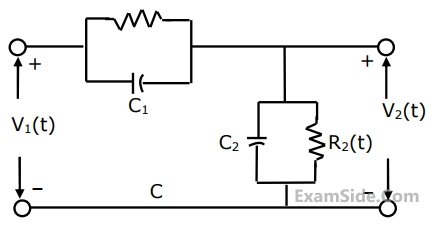
For the compensated attenuator of figure, the impulse response under the condition $$R_1C_1\;=\;R_2C_2$$ is:
If the Laplace transform of the voltage across a capacitor of value of $$\frac12\;\mathrm F$$ is $$V_C\;\left(s\right)\;=\;\frac{s\;+\;1}{s^3\;+\;s^2\;+\;s\;+\;1}$$ , the value of the current through the capacitor at t = 0+ is
A 10 Ω resistor, a 1 H inductor and 1 $$\mathrm{μF}$$ capacitor are connected in parallel.The combination is driven by a unit step current.Under the steady state condition, the source current flows through
A square waveform as shown in the figure is applied across 1 mH ideal inductor.The current through the inductor is a triangular wave of ................. peak amplitude.

Marks 3

Marks 5
(a) Determine $${V_C}\left( {{0^ + }} \right)$$ and $${I_{_L}}\left( {{0^ + }} \right)$$
(b) Determine $${{d{V_C}\left( t \right)} \over {dt}}\,\,$$ at $$t\, = \,{0^ + }$$
(c) Determine $${{V_C}\left( t \right)}$$ for $$t > 0$$
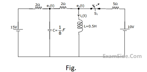
(a) Find $${i_L}\left( {{0^ + }} \right)$$.
(b) Find $${e_1}\left( {{0^ + }} \right)$$.
(c) Using nodal equations and Laplace transform approach, find an expression
for the voltage across the capacitor for all $$t\, = \,0$$.
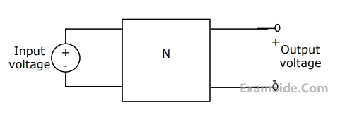
(a) Find the voltage transfer function of the network.
(b) Find L, and draw the configuration of the network.
(c) Find the impulse response of the network.
 n
n
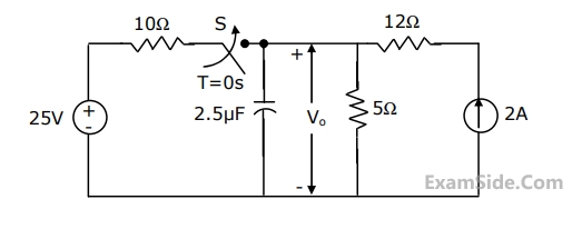
(a) Find $${V_0}$$ for $$t \le 0$$ and as $$t \to \infty $$.
(b) Write an expression for $${V_0}$$ as a function of time for $$0 \le t \le \infty $$.
(c) Evaluate $${V_0}$$ at $$t = 25\,\,\mu $$sec.
(1) Determine the initial voltage, VC(0-), across the capacitor, and the initial current, iL(0-) , through the indicator.
(2) Calculate the voltage, VL(t) , across the inductance for t > 0.