Transmission Lines · Electromagnetics · GATE ECE
Marks 1
For a lossless passive two-port network, $\left|S_{11}\right|$ and $\left|S_{21}\right|$ intersect at -3 dB .
For a lossy passive two-port network, $\left|S_{11}\right|$ and $\left|S_{21}\right|$ intersect at -4 dB ..
The percentage of power dissipated in the lossy network at the intersection frequency is $\_\_\_\_$ .
(rounded off to two decimal places)
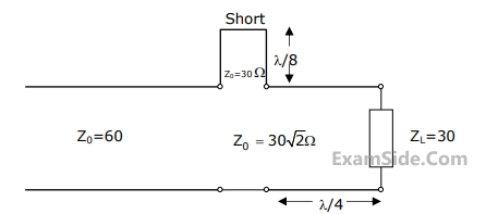
Consider a lossless transmission line terminated with a short circuit as shown in the figure below. As one moves towards the generator from the load, the normalized impedances $Z_{inA}$, $Z_{inB}$, $Z_{inC}$, and $Z_{inD}$ (indicated in the figure) are ______.

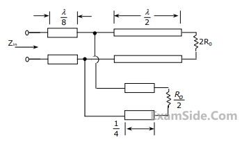
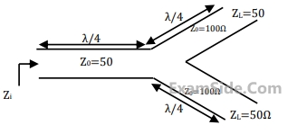
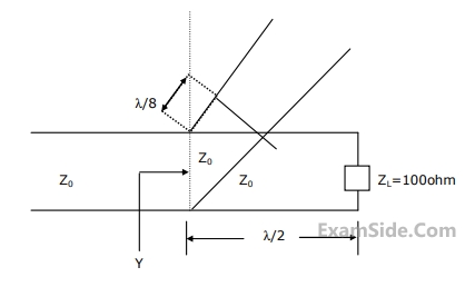
The impedance matching Network shown in figure is to match a lossless line having characteristic impedance $Z_o= 50 \Omega$ with a load impedance $Z_L$. A quarter - Wave line having a characteristic impedance $Z_1=75 \Omega$ is connected to $Z_L$. Two stubs having characteristic impedance of $75 \Omega$ each are connected to this quarter - wave line. One is a short - circuited (S.C) stub of length $0.25 \lambda$ connected across PQ and the other one in an open - Circuted (O.C) stub of length 0.5 $\lambda$ connected across RS.
 The impedance matching is achieved when the real part of $Z_L$ is
A transmission line of length $3 \lambda / 4$ and having a characteristic impedance of $50 \Omega$ is terminated with a load of $400 \Omega$. The impedance (rounded off to two decimal places) seen at the input end of the transmission line is $\_\_\_\_$ $\Omega$.
The impedances $Z=j X$, for all $X$ in the range ( $-\infty, \infty$ ), map to the Smith chart as

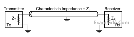 Which one of the following statements is TRUE about the distortion of the received signal due to impedance mismatch?
$$H/m,\,\,{\varepsilon _0} = {{{{10}^{ - 9}}\,} \over {36\,\pi }}\,F/m,$$ the characteristic impedance of the cable is

Marks 2
A complex load (in $\Omega$ ) is represented as $\Gamma_L=0.5 \angle 30^{\circ}$ on the Smith chart. A co-axial cable with a characteristic impedance of $50 \Omega$ is connected to the load. The new input impedance of the load now moves to a diametrically opposite point on the same $\Gamma$ circle on the Smith chart.
Which option is the nearest input impedance of the cable connected load (in $\Omega$ )?
A lossless transmission line with characteristic impedance $Z_0 = 50 \Omega$ is terminated with an unknown load. The magnitude of the reflection coefficient is $|\Gamma| = 0.6$. As one moves towards the generator from the load, the maximum value of the input impedance magnitude looking towards the load (in $\Omega$) is _________.
The standing wave ratio on a 50 $$\Omega$$ lossless transmission line terminated in an unknown load impedance is found to be 2.0. The distance between successive voltage minima is 30 cm and the first minimum is located at 10 cm from the load. $$Z_L$$ can be replaced by an equivalent length $$l_m$$ and terminating resistance $$R_m$$ of the same line. The value of $$R_m$$ and $$l_m$$, respectively, are

The following circuit(s) representing a lumped element equivalent of an infinitesimal sectioin of a transmission line is/are


 Which one of the following inequalities is always satisfied?


 The value of the load resistance is
The reflection coefficient is given by
The value of the load resistance is
The reflection coefficient is given by 

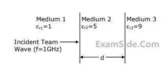
Marks 5
(a) Wave impedance in mediums 2 and 3.
(b) d such that medium 2 acts as a quarter wave $$(\lambda /40$$)transformer.
(c) Reflection coefficient $$(\Gamma )$$ and voltage standing wave ratio (VSWR) at the interface of the medium 1 and 2, when $$d = \lambda /4$$.