Network Elements · Network Theory · GATE ECE
Marks 1
The current I in the circuit shown is _________.

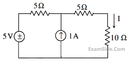
Consider the circuit shown in the figure. The current I flowing through the 10 $$\Omega$$ resister is ___________.

Consider the circuit shown in the figure.

The current I flowing through the 7$$\Omega$$ resistor between P and Q (rounded off to one decimal place) is ______ A
A connection is made consisting of resistance A in series with a parallel combination of resistances B and C. Three resistors of value 10 Ω, 5 Ω, 2 Ω are provided. Consider all possible permutations of the given resistors into the positions A, B, C, and identify the configurations with maximum possible overall resistance, and also the ones with minimum possible overall resistance. The ratio of maximum to minimum values of the resistances (up to second decimal place) is ____________.
In the given circuit, the values of V1 and V2 respectively are

Consider the configuration shown in the figure which is a portion of a larger electrical network

For R = 1 Ω and currents i1 = 2A, i4 = -1A, i5 = -4A, which one of the following is TRUE?
The circuit shown in the figure represents a
In the figure shown, the value of the current I (in Amperes) is __________.
Consider a delta connection of resistors and its equivalent star connection as shown below. If all elements of the delta connection are scaled by a factor k, k > 0, the elements of the corresponding star equivalent will be scaled by a factor of

The impedance looking into nodes 1 and 2 in the given circuit is

In the circuit shown below, current through the inductor is

In the interconnection of ideal sources shown in the figure, it is known that the 60V source is absorbing power.

Which of the following can be the value of the current source I?
The equivalent inductance measured between the terminals 1 and 2 for the circuit shown in figure, is

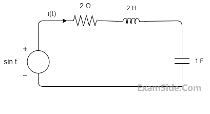
The differential equation for the current i(t) in the circuit of Fig. is
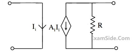
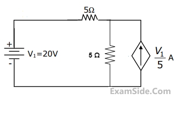
The dependent current source shown in Figure
The voltage e0 in Fig. is

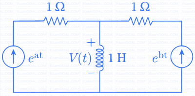
In the circuit of Fig., the votage v(t) is
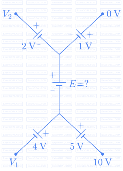
In the circuit of Fig., the value of the voltage source E is
The Nodal method of circuit analysis is based on
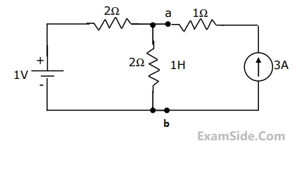
The voltage across the terminals a and b in Fig. is
The voltage V in Fig. is equal to

The voltage V in Fig. is always equal to

The voltage V in Fig. is

The current "i4" in the circuit of Fig. is equal to

Two 2H inductance coils are connected in series and are also magnetically coupled to each other the coefficient of coupling being 0.1.The total inductance of the combination can be
A dc circuit shown in figure has a voltage source V, a current source I and several resistors. A particular resistor R dissipates a power of 4 Watts when V alone is active. The same resistor R dissipates a power of 9 Watts when I alone is active. The power dissipated by R when both sources are active will be

Marks 2
Consider the network shown below with R1 = 1 $$\Omega $$, R2 = 2 $$\Omega $$ and R3 = 3 $$\Omega $$. The network is connected to a constant voltage source of 11 V.

The magnitude of the current (in amperes, accurate to two decimal places) through the source is _______.
In the circuit shown in the figure, the magnitude of the current (in amperes) through R2 is___________.

In the given circuit, each resistor has a value equal to 1 Ω.

What is the equivalent resistance across the terminals a and b?
In the figure shown, the current i (in ampere) is ______.

A Y-network has resistances of 10Ω each in two of its arms, while the third arm has a resistance of 11Ω in the equivalent ∆ − network, the lowest value (in Ω) among the three resistances is ______________.
In the magnetically coupled circuit shown in the figure, 56 % of the total flux emanating from one coil links the other coil. The value of the mutual inductance (in H) is ______ .

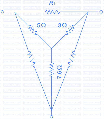
For the Y-network shown in the figure, the value of R1 (in Ω) in the equivalent ∆ -network is ________.
Two magnetically uncoupled inductive coils have Q factors q1 and q2 at the chosen operating frequency. Their respective resistances are R1 and R2. When connected in series, their effective Q factor at the same operating frequency is
Consider the following figure
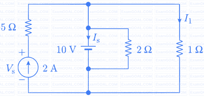
The current IS in Amps in the voltage source, and voltage VS in Volts across the current source respectively, are
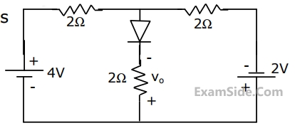
Consider the following figure
The current in the 1Ω resistor in Amps is
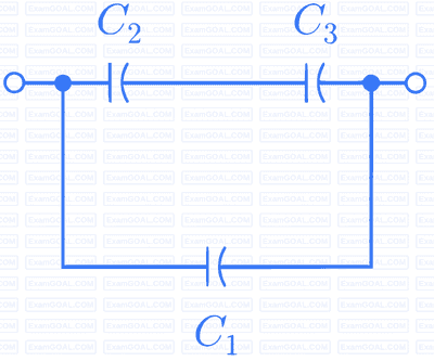
Three capacitors C1 ,C2 and C3 whose values are 10 µF, 5µF and 2µF respectively, have breakdown voltages of 10V, 5V, and 2V respectively. For the interconnection shown below, the maximum safe voltage in Volts that can be applied across the combination, and the corresponding total charge in µC stored in the effective capacitance across the terminals are respectively.
If VA - VB = 6 V then VC - VD is


In the circuit shown, the power supplied by the voltage source is

Impedance Z as shown in the figure is:

The rms value of the periodic waveform given in figure is

Twelve 1Ω resistances are used as edges to form a cube. The resistance between two diagonally opposite corners of the cube is
For the circuit in Fig. the voltage V0 is
The two electrical sub-network N1 and N2 are connected through three resistors as shown in figure. The voltage across 5 Ω resistor and 1 Ω resistor are given to be 10 V and 5 V, respectively. Then voltage across 15 Ω resistor is

A network contains linear resistors and ideal voltage sources. If values of all the resistors are doubled, then the voltage across each resistor is
Of the four networks, N1,N2, N3 and N4 of figure, the networks having identical driving point functions are

