Two Port Networks · Network Theory · GATE ECE
Marks 1
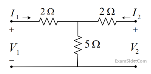
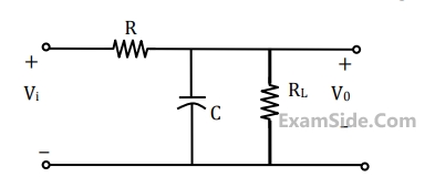
For the two port network shown below, the [Y]-parameters is given as
$$[Y] = {1 \over {100}}\left[ {\matrix{ 2 & { - 1} \cr { - 1} & {4/3} \cr } } \right]S$$
The value of load impedance $$\mathrm{Z_L}$$, in $$\Omega$$, for maximum power transfer will be ___________ (rounded off to the nearest integer).

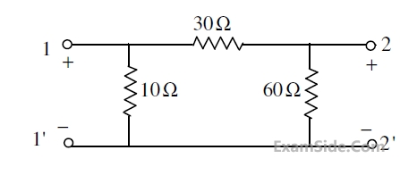
$$ \text { Consider the two-port network shown in the figure. } $$
 The admittance parameters, in siemens are
In the given circuit, the two-port network has the impedance matrix $[Z]=\left[\begin{array}{cc}40 & 60 \\ 60 & 120\end{array}\right]$. The value of $Z_L$ for which maximum power is transferred to the load is $\_\_\_\_$ $\Omega$.

$$\left[ {\matrix{ {{V_1}} \cr {{I_1}} \cr } } \right] = \left[ {\matrix{ A & B \cr C & D \cr } } \right]\left[ {\matrix{ {{V_2}} \cr { - {I_2}} \cr } } \right]$$
The parameter B for the given two-port network (in ohms, correct to two decimal places) is _______.
 Then the value of $${R_b}$$ (in $$\Omega $$) equals _______________________3
The value of the load resistance $${R_L}$$ is


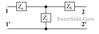
The open circuit impedance matrix of the 2-port network shown in figure is

Marks 2
Consider the two-port network as shown in the Figure.
Which of the following options provides the correct set of values of $A, B, C$ and $D$ parameters?

The $Z$-parameter matrix of a two port network relates the port voltages and port currents as follows:
$$ \left[\begin{array}{l} V_1 \\ V_2 \end{array}\right]=Z\left[\begin{array}{l} I_1 \\ I_2 \end{array}\right] $$
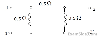
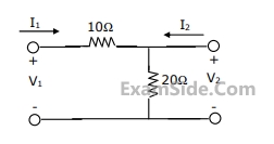
The Z-parameter matrix (with each entry in Ohms) of the network shown below is
___________.

For the two port network shown below, the value of the $Y_{21}$ parameter (in Siemens) is ______.

The h-parameters of a two port network are shown below. The condition for the maximum small signal voltage gain $${{{V_{out}}} \over {{V_s}}}$$ is

The S-parameters of a two port network is given as
$$[S] = \left[ {\matrix{ {{S_{11}}} & {{S_{12}}} \cr {{S_{21}}} & {{S_{22}}} \cr } } \right]$$
with reference to $${Z_0}$$. Two lossless transmission line sections of electrical lengths $${\theta _1} = \beta {l_1}$$ and $${\theta _2} = \beta {l_2}$$ are added to the input and output ports for measurement purposes, respectively. The S-parameters $$[S']$$ of the resultant two port network is

A linear 2-port network is shown in Fig. (a). An ideal DC voltage source of 10 V is connected across Port 1. A variable resistance R is connected across Port 2. As R is varied, the measured voltage and current at Port 2 is shown in Fig. (b) as a V2 versus $$-$$I2 plot. Note that for V2 = 5 V, I2 = 0 mA, and for V2 = 4 V, I2 = $$-$$4 mA. When the variable resistance R at Port 2 is replaced by the load shown in Fig. (c), the current I2 is ________ mA (rounded off to one decimal place).


For a 2-port network consisting of an ideal lossless transformer, the parameter $S_{21}$ (rounded off to two decimal places) for a reference impedance of $10 \Omega$ is $\_\_\_\_$ .


The equivalent resistance in the infinite ladder network shown in the figure, is$${R_e}$$

The value of $${R_e}/R$$ is _______________


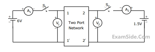
(i) $${S_1} - open,\,\,\,\,{S_2} - closed$$
$${A_1} = 0\,A,\,\,\,\,\,\,{V_1} = \,4.5\,\,V,$$
$${V_2}\, = \,1.5\,V,\,\,\,\,{A_2}\, = \,1\,A$$
(ii) $${S_1} - Closed,\,\,\,\,{S_2} - Open$$
$${A_1} = 4\,A,\,\,\,\,\,\,{V_1} = \,6\,\,V,$$
$${V_2}\, = \,6\,V,\,\,\,\,{A_2}\, = \,0\,A$$
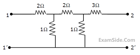
 The z-parameter matrix for this network is
 (i) $${S_1} - open,\,\,\,\,{S_2} - closed$$
$${A_1} = 0\,A,\,\,\,\,\,\,{V_1} = \,4.5\,\,V,$$
$${V_2}\, = \,1.5\,V,\,\,\,\,{A_2}\, = \,1\,A$$
(ii) $${S_1} - Closed,\,\,\,\,{S_2} - Open$$
$${A_1} = 4\,A,\,\,\,\,\,\,{V_1} = \,6\,\,V,$$
$${V_2}\, = \,6\,V,\,\,\,\,{A_2}\, = \,0\,A$$
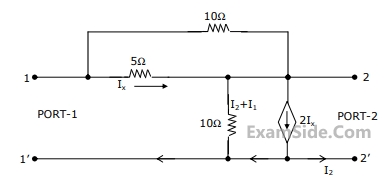
The h-parameter matrix for this network is 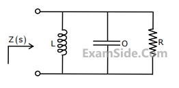
A two-port network is represented by ABCD parameters given by
$$\left[ {\matrix{ {{V_1}} \cr {{I_1}} \cr } } \right] = \,\left[ {\matrix{ A & B \cr C & D \cr } } \right]\,\left[ {\matrix{ {{V_2}} \cr { - \,{I_2}} \cr } } \right]$$
If port-2 is terminated by $${R_L}$$, the input impedance seen at port-1 is given by

If R1 = R2 = R4 = R and R3 = 1.1R in the bridge circuit shown in figure, then the reading in the ideal voltmeter connected between a and b is

$$Z\,\left[ {\matrix{ {{Z_{11}}} & {{Z_{12}}} \cr {{Z_{21}}} & {{Z_{22}}} \cr } } \right]\,$$ are


Marks 5

(a) Find its short-circuit admittance parameters.
(b) Find the open-ciruit impedance $${Z_{22}}$$.
(a) $${E_1} = \,10\,\angle \,{0^{ \circ \,}}\,V$$
(b) $${I_1} = \,10\,\angle \,{0^{ \circ \,}}\,A$$
(c) A source $$10\,\angle \,{0^{ \circ \,}}\,V$$ in series with a 0.25 $$\Omega $$ resistor is connected to the input port.

Write down the short circuit admittance matrix $${{Y_{SC}}}$$ of the network viewed as a two-port network, but now taking B as the input terminal, C as the output terminal and A as the common terminal.

$${{{V_0}\,(s)} \over {{V_s}\,(s)}} = - {1 \over {{{(CR\,s)}^2}}}$$, assume ideal OP-Amp


$$T(s) = {{{V_2}\,(s)} \over {{V_1}\,(s)}} = \,{K \over {{s^2} + \,(3 - K)\,s + 1}}$$

