Marks 2

Marks 5
1
For the circuit in Fig., write the state equations using vc
and iL as state variables.
GATE ECE 2000
2
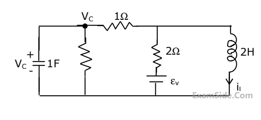
 For the circuit shown in Fig. choose state variables $$X_1,\;X_2,\;X_3$$ to be $$i_{L1}\left(t\right),\;v_{C2}\left(t\right),\;i_{L3}\left(t\right)$$
(a) Write the state equations
$$$\begin{bmatrix}{\dot X}_1\\{\dot X}_2\\{\dot X}_3\end{bmatrix}\;=\;A\;\begin{bmatrix}X_1\\X_2\\X_3\end{bmatrix}\;+\;B\left[e\left(t\right)\right]$$$(b) If e(t) = 0, t $$\geq$$ 0, $$i_{L1}\left(0\right)\;=\;0,\;v_{C2}\left(0\right)\;=\;0,\;i_{L3}\left(0\right)\;=\;1A,$$ then what would the total energy dissipated in the registors in the interval $$\left(0,\infty\right)$$ be
GATE ECE 1997
3
Refer to the circuit shown in Fig.
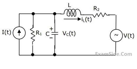 Choosing the voltage vC(t) across capacitor, and the current iL(t) through the inductor as state variable,i.e.,
$$$\left[\mathrm x\left(\mathrm t\right)\right]\;=\;\begin{bmatrix}{\mathrm v}_\mathrm C\left(\mathrm t\right)\\{\mathrm i}_\mathrm L\left(\mathrm t\right)\end{bmatrix}$$$
Write the state equation in the form $$\frac{\operatorname d\left[x\left(t\right)\right]}{\operatorname dt}\;=\;\left[A\right]\left[x\left(t\right)\right]\;+\;\left[B\right]\left[u\left(t\right)\right]$$ and find [A], [B] and [u(t)].
Choosing the voltage vC(t) across capacitor, and the current iL(t) through the inductor as state variable,i.e.,
$$$\left[\mathrm x\left(\mathrm t\right)\right]\;=\;\begin{bmatrix}{\mathrm v}_\mathrm C\left(\mathrm t\right)\\{\mathrm i}_\mathrm L\left(\mathrm t\right)\end{bmatrix}$$$
Write the state equation in the form $$\frac{\operatorname d\left[x\left(t\right)\right]}{\operatorname dt}\;=\;\left[A\right]\left[x\left(t\right)\right]\;+\;\left[B\right]\left[u\left(t\right)\right]$$ and find [A], [B] and [u(t)].GATE ECE 1996