Network Theorems · Network Theory · GATE ECE
Marks 1
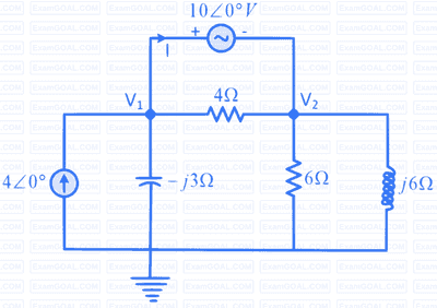
The output voltage $V_o$ (in Volt) for the network given in the Figure is $\_\_\_\_$ . (rounded off to two decimal places)

Consider a part of an electrical network as shown below. Some node voltages, and the current flowing through the $3 \Omega$ resistor are as indicated.
The voltage (in Volts) at node $X$ is __________ .

In the given circuit, the current $I_x$ (in mA) is _______ .

In the circuit shown below, the current i flowing through 200 $$\Omega$$ resistor is __________ mA (rounded off to two decimal places).


The value of v0 (rounded off to one decimal place) is ______ V.
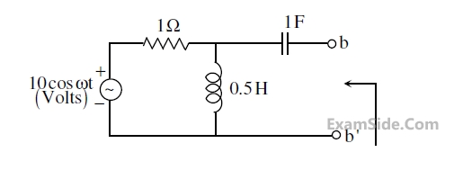
$$ \text { In the circuit shown below, the Thevenin voltage } V_{\text {th }} \text { is } $$

Consider the two-port resistive network shown in the figure. When an excitation of 5 V is applied across Port 1, and Port 2 is shorted, the current through the short circuit at Port 2 is measured to be 1 A (see (a) in the figure).
Now, if an excitation of 5 V is applied across Port 2, and Port 1 is shorted (see (b) in the figure), what is the current through the short circuit at Port 1?


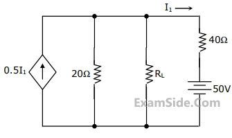
The value of IL that maximizes the power absorbed by the constant current load is


In the network shown in the figure, all resistors are identical with R = 300 $$\Omega$$. The resistance Rab (in $$\Omega$$) of the network is _______.

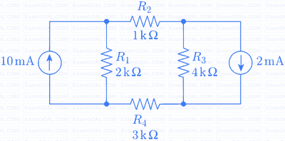
The magnitude of current (in mA) through the resistor R2 in the figure shown is _____.


A fully charged mobile phone with a 12 V battery is good for a 10 minute talk-time. Assume that, during the talk-time, the battery delivers a constant current of 2 A and its voltage drops linearly from 12 V to 10 V as shown in the figure. How much energy does the battery deliver during this talk-time?


Superposition theorem is NOT applicable to networks containing
The value of the resistance, R, connected across the terminals, A and B, (ref. Fig.), which will absorb the maximum power, is

A generator of internal impedance, ZG, delivers maximum power to a load impedance, ZL, only if ZL = ................
If the secondary winding of the ideal transformer shown in the circuit of the figure has 40 turns, the number of turns in the primary winding for maximum power transfer to the 2 Ω resistor will be

Marks 2
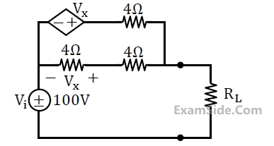
In the network shown below, maximum power is to be transferred to the load $R_L$.

The value of $R_L$ (in Ω) is ______.
Consider the circuit shown in the figure.

The Thevenin equivalent resistance (in Ω) across P – Q is _________.
In the circuit shown in the figure, the maximum power (in watt) delivered to the resistor R is _________.

In the circuit shown, the Norton equivalent resistance (in Ω) across terminals a–b is ___________.


(i) 1Ω connected at port B draws a current of 3 A
(ii) 2.5Ω connected at port B draws a current of 2 A

For the same network, with 6 V dc connected at port A, 1Ω connected at port B draws 7/3 A. If 8 V dc is connected to port A, the open circuit voltage at port B is
(i) 1Ω connected at port B draws a current of 3 A
(ii) 2.5Ω connected at port B draws a current of 2 A
With 10 V dc connected at port A, the current drawn by 7Ω connected at port B is


For the circuit shown in figure, Thevenin’s voltage and Thevenin’s equivalent resistance at terminals a – b is

In the network of Figure, the maximum power is delivered to RL if its value is
In figure, the value of the load resistor R which maximizes the power delivered to it is

The voltage e0 in figure is

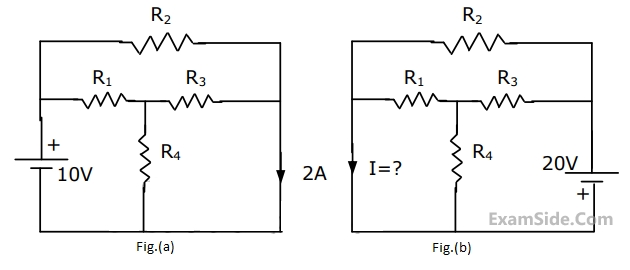
Use the data of Fig.(a). The current i in the circuit of Fig.(b) is
The Thevenin equivalent voltage VTH appearing between the terminals A and B of the network shown in Fig. is given by

The value of R (in ohms) required for maximum power transfer in the network shown in Fig. is

A DC circuit shown in the figure has a voltage source V, a current source I and several resistors. A particular resistor R dissipates a power of 4 Watts when V alone is active. The same resistor R dissipates a power of 9 Watts when I alone is active. The power dissipated by R when both sources are active will be


In the circuit of figure, the power dissipated in the register R is 1W when only source '1' is present and '2' replaced by a short.The power dissipated in the same registor R is 4W when only source '2' is present and '1' is replaced by a short.When both the source '1' and '2' are present, the power dissipated in R will be:

A load, ZL = RL + jXL is to be matched, using an ideal transformer, to a generator of internal impedance, ZS = RS + jXS. The turns ratio of the transformer required is
If an impedance ZL is connected across a voltage source V with source impedance ZS, then for maximum power transfer, the load impedance must be equal to
Marks 5
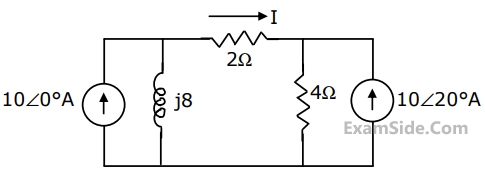
For the network shown in Fig., evaluate the current I flowing through the 2Ω resistor using superposition theorem.
A voltage source of internal impedance $${\mathrm R}_\mathrm s\;+\;{\mathrm{jX}}_\mathrm s$$ supplies power to a load of impedance $${\mathrm R}_\mathrm L\;+\;{\mathrm{jX}}_\mathrm L$$ in which only $${\mathrm R}_\mathrm L$$ is variable. Determine the value of $${\mathrm R}_\mathrm L$$ for maximum power transfer from the source to the load. Also, find the numerical value of $${\mathrm R}_\mathrm L$$ if the source impedance is 3.0 Ω (purely resistive) and $${\mathrm X}_\mathrm L$$ is 4.0 Ω.
In the circuit of Fig. when R = 0 Ω, the current iR equals 10 A.
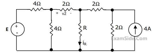
(a) Find the value of R for which it absorbs maximum power.
(b) Find the value of E.
(c) Find v2 when R = $$\infty$$ ( open circuit)
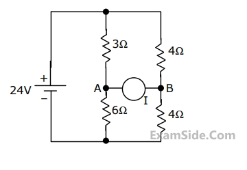
In the circuit shown in Fig., it is known that the variable current source I absorbs power.Find I (in magnitude and direction) so that it receives maximum power and also find the amount of power absorbed by it.
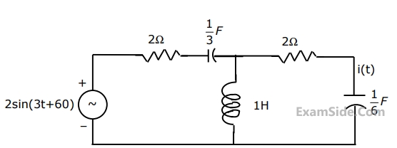
Determine the current, i(t), in the circuit given below, (Fig.), using the Thevenin's theorem.