Frequency Response · Analog Circuits · GATE ECE
Marks 1
1
All the components in the bandpass filter given below are ideal. The lower -3 dB frequency of the filter is 1 MHz .
The upper -3 dB frequency (in MHz, rounded off to the nearest integer) is ___________ .

GATE ECE 2025
2
The Miller effect in the context of a Common Emitter amplifier explains
GATE ECE 2017 Set 1
3
Which one of the following statements is correct about an ac-coupled common- emitter amplifier operating in the mid-band region?
GATE ECE 2016 Set 2
4
Generally, the gain of a transistor Amplifier falls at high frequency due to the
GATE ECE 2003
5
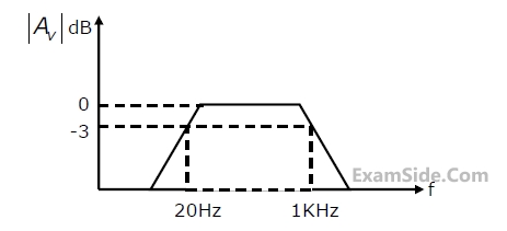
Three identical RC-Coupled transistor amplifiers are cascaded. If each of the
amplifiers has a frequency response as shown in figure, the overall frequency
response is as given as
GATE ECE 2002
6
The current gain of a bipolar transistor drops at high frequencies because of
GATE ECE 2000
7
The $${f_T}$$ of a BJT is related to its $${g_{m,}}\,\,{C_\pi }$$ and $${C_\mu }$$ as follows
GATE ECE 1998
8
An npn transistor has a beta cut-off frequency $${f_\beta }$$ of 1MHz and Common Emitter short circuit low frequency current gain $${\beta _o}$$ of 200. The unity gain frequency $${f_T}$$ and the alpha cut-off frequency $${f_\alpha }$$ respectively are
GATE ECE 1996
9
An RC-Coupled Amplifier is assumed to have a single-pole low frequency transfer function. The maximum lower-cutoff frequency allowed for the Amplifier to pass 50 Hz square wave with no more than 10% tilt is ______.
GATE ECE 1995
10
An Amplifier has an open-loop gain of 100 and its lower and upper-cut-off frequency of 100 Hz and 100 kHz respectively, a feedback network with a feedback factor of 0.99 is connected to the amplifier. the lower-and upper-cut-off frequency's are at ............and ............
GATE ECE 1995
11
In a multi-stage RC-Coupled Amplifier the coupling capacitor.
GATE ECE 1993
Marks 2
1
The components in the circuit given below are ideal. If $R=2 \mathrm{k} \Omega$ and $C=1 \mu \mathrm{~F}$, the -3 dB cut-off frequency of the circuit in Hz is

GATE ECE 2020
2
Consider the common emitter amplifier shown below with the following circuit parameters:
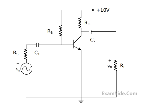
$$\beta = 100,\,{g_m} = 0.3861\,{\rm A}/V,\,{r_0} = \infty ,\,{r_\pi } = 259\,\Omega, $$
$${R_s} = 1\,K\Omega ,{R_B} = 93\,K\Omega ,\,{R_C} = 250\,\Omega, $$
$${R_L} = 1\,K\Omega ,\,{C_1} = \infty \,\,and\,\,{C_2} = 4.7\,\mu F.$$
The Resistance seen by the source Vs is
GATE ECE 2010
3
Consider the common emitter amplifier shown below with the following circuit parameters:
$$\beta = 100,\,{g_m} = 0.3861\,{\rm A}/V,\,{r_0} = \infty ,\,{r_\pi } = 259\,\Omega, $$
$${R_s} = 1\,K\Omega ,{R_B} = 93\,K\Omega ,\,{R_C} = 250\,\Omega, $$
$${R_L} = 1\,K\Omega ,\,{C_1} = \infty \,\,and\,\,{C_2} = 4.7\,\mu F.$$
The lower cut-off frequency due to C2 is
GATE ECE 2010
4
An npn BJT has gm = 38 mA/V, $${C_\mu }\, = {10^{ - 14}}$$ F, $${C_\pi }\, = 4\, \times {10^{ - 13}}\,F$$ and DC current gain $$\beta \, = \,90$$. For this transistor fT and $${f_\beta }$$ are
GATE ECE 2001
5
An NPN transistor (with $${C_\pi }\,\, = \,\,0.3\,\,$$ pf) has a unity gain cutoff frequency $${f_T}$$ of 400 MHz at a DC-bias current Ic = 1mA. The value of its $${C_\mu }$$ (in pf) is approximately $$\left( {{V_T}\, = \,26\,mV} \right)$$.
GATE ECE 1999
6
An amplifier is assumed to have a single pole high frequency transfer function.
The rise time of its output response to a step function input is 35 nsec. The upper 3 dB frequency (in MHz) for the amplifier to a sinusoidal input is approximately at
GATE ECE 1999
7
In the circuit shown in Fig. is a finite gain amplifier with a gain of K, a very large input impedance, and a very low output impedance. The input impedance of the feedback amplifier with the feedback impedance Z conducted as shown will be

GATE ECE 1996
