1
GATE ECE 2001
MCQ (Single Correct Answer)
+2
-0.6
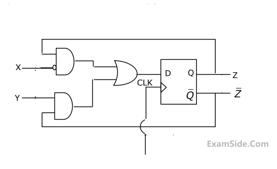
The digital block in the figure is realized using two positive edge triggered D flip-flops. Assume that for t < t0, Q1 = Q2 =0. The circuit in the digital block is given by

A

B

C

D

2
GATE ECE 2000
MCQ (Single Correct Answer)
+2
-0.6
In the figure, the J and K inputs of all the four Flip-Flops are made high. The frequency of the signal at output Y is 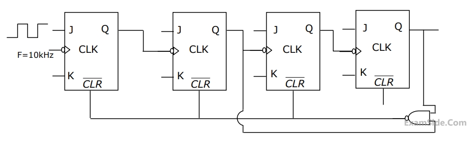
3
GATE ECE 2000
MCQ (Single Correct Answer)
+2
-0.6
A sequential circuit using D flip-flop and logic gates is shown in the figure, where X and Y are the inputs and Z is the output. The circuit is
4
GATE ECE 1999
MCQ (Single Correct Answer)
+2
-0.6
The ripple counter shown in the figure works as a

GATE ECE Subjects
Browse all chapters by subject
Control Systems
Engineering Mathematics
Analog Circuits
Network Theory
Electromagnetics
Electronic Devices and VLSI
Digital Circuits
Microprocessors
Signals and Systems
Representation of Continuous Time Signal Fourier Series Fourier Transform Continuous Time Signal Laplace Transform Discrete Time Signal Fourier Series Fourier Transform Discrete Fourier Transform and Fast Fourier Transform Discrete Time Signal Z Transform Continuous Time Linear Invariant System Discrete Time Linear Time Invariant Systems Transmission of Signal Through Continuous Time LTI Systems Sampling Transmission of Signal Through Discrete Time Lti Systems Miscellaneous
Communications
General Aptitude