1
GATE ECE 2012
MCQ (Single Correct Answer)
+2
-0.6
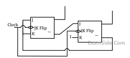
The state transition diagram for the logic circuit shown is

A

B

C

D

2
GATE ECE 2011
MCQ (Single Correct Answer)
+2
-0.6
The output of a 3-stage Johnson (twisted-ring) counter is fed to a digital-to-analog (D/A) converter as shown in the figure below. Assume all the states of the counter to be unset initially. The waveform which represents the D/A converter output Vo is

A

B

C

D

3
GATE ECE 2011
MCQ (Single Correct Answer)
+2
-0.6
Two D flip-flops are connected as a synchronous counter that goes through the following QB QA sequence $$00 \to 11 \to 01 \to 10 \to 00 \to ......$$
4
GATE ECE 2009
MCQ (Single Correct Answer)
+2
-0.6
What are the counting states (Q1, Q2) for the counter shown in the figure below?
GATE ECE Subjects
Browse all chapters by subject
General Aptitude
Network Theory
Microprocessors
Signals and Systems
Discrete Time Signal Fourier Series Fourier Transform Continuous Time Signal Laplace Transform Fourier Transform Discrete Fourier Transform and Fast Fourier Transform Representation of Continuous Time Signal Fourier Series Discrete Time Linear Time Invariant Systems Transmission of Signal Through Continuous Time LTI Systems Transmission of Signal Through Discrete Time Lti Systems Miscellaneous Continuous Time Linear Invariant System Discrete Time Signal Z Transform Sampling
Electromagnetics
Digital Circuits
Electronic Devices and VLSI
Control Systems
Communications
Engineering Mathematics