1
GATE ECE 2017 Set 1
MCQ (Single Correct Answer)
+2
-0.6
A finite state machine (FSM) is implemented using the D flip-flops A and B and logic gates, as shown in the figure below. The four possible states of the FSM are QA QB = 00, 01, 10, and 11.
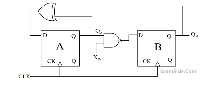
Assume that XIN is held at a logic level throughout the operation of the FSM. When the FSM is initialized to the state QA QB = 100 and clocked, after a few clock cycles, it starts cycling through
2
GATE ECE 2017 Set 1
Numerical
+2
-0
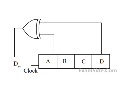
A 4-bit shift register circuit configured for right-shift operation is $${D_{in}}\, \to \,A,\,A\, \to B,\,B \to C,\,C \to D,$$ is shown. If the present state of the shift register is ABCD = 1101, the number of clock cycles required to reach the state ABCD = 1111 is
Your input ____
3
GATE ECE 2016 Set 2
MCQ (Single Correct Answer)
+2
-0.6
For the circuit shown in the figure, the delay of the bubbled NAND gate is 2ns and that of the counter is assumed to be zero

If the clock (Clk) frequency is 1 GHz, then the counter behaves as a
4
GATE ECE 2016 Set 2
MCQ (Single Correct Answer)
+2
-0.6
The state transition diagram for a finite state machine with states A, B and C, and binary inputs X, Y and Z, is shown in the figure.

Which one of the following statements is correct?
GATE ECE Subjects
Browse all chapters by subject
Network Theory
Control Systems
Electronic Devices and VLSI
Analog Circuits
Digital Circuits
Microprocessors
Signals and Systems
Representation of Continuous Time Signal Fourier Series Fourier Transform Continuous Time Signal Laplace Transform Discrete Time Signal Fourier Series Fourier Transform Discrete Fourier Transform and Fast Fourier Transform Discrete Time Signal Z Transform Continuous Time Linear Invariant System Discrete Time Linear Time Invariant Systems Transmission of Signal Through Continuous Time LTI Systems Sampling Transmission of Signal Through Discrete Time Lti Systems Miscellaneous
Communications
Electromagnetics
General Aptitude