1
GATE ECE 2012
MCQ (Single Correct Answer)
+2
-0.6
The state variable description of an LTI system is given by
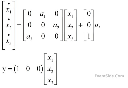
where y is the output and u is input. The system is controllable for
2
GATE ECE 2011
MCQ (Single Correct Answer)
+2
-0.6
The block diagram of a system with one input u and two outputs y1 and y2 is given below
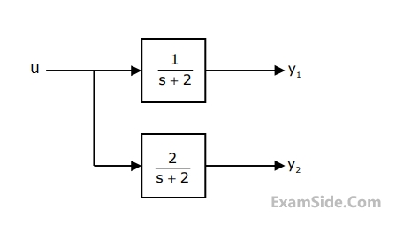
A state space model of the above system in terms of the state vector $$\underline x $$ and the output vector $$\underline y = {\left[ {\matrix{ {{y_1}} & {{y_2}} \cr } } \right]^\tau }$$ is
3
GATE ECE 2010
MCQ (Single Correct Answer)
+2
-0.6
The signal flow graph of a system is shown below.
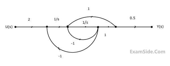
The state variable representation of the system can be
4
GATE ECE 2010
MCQ (Single Correct Answer)
+2
-0.6
The signal flow graph of a system is shown below.
The transfer function of the system is
GATE ECE Subjects
Browse all chapters by subject
Network Theory
Control Systems
Electronic Devices and VLSI
Analog Circuits
Digital Circuits
Microprocessors
Signals and Systems
Representation of Continuous Time Signal Fourier Series Fourier Transform Continuous Time Signal Laplace Transform Discrete Time Signal Fourier Series Fourier Transform Discrete Fourier Transform and Fast Fourier Transform Discrete Time Signal Z Transform Continuous Time Linear Invariant System Discrete Time Linear Time Invariant Systems Transmission of Signal Through Continuous Time LTI Systems Sampling Transmission of Signal Through Discrete Time Lti Systems Miscellaneous
Communications
Electromagnetics
General Aptitude