1
GATE ECE 2013
MCQ (Single Correct Answer)
+2
-0.6
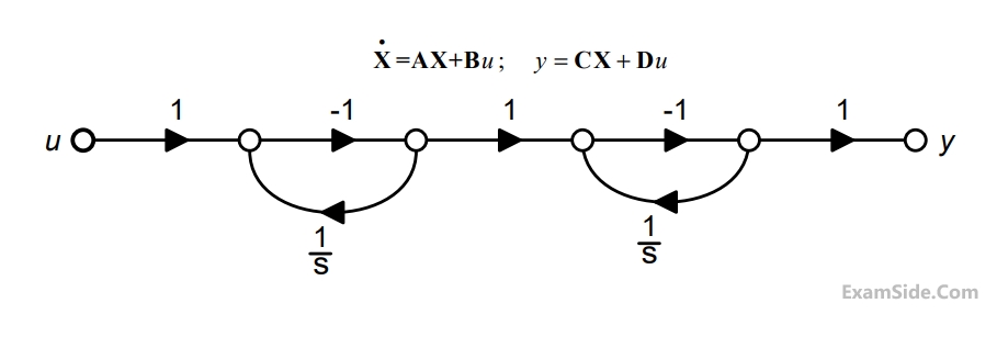
The state diagram of a system is shown below. A system is shown below. A system is described by the state variable equations


The state-variable equations of the system shown in the figure above are
2
GATE ECE 2013
MCQ (Single Correct Answer)
+2
-0.6
The state diagram of a system is shown below. A system is shown below. A system is described by the state variable equations


The state transition matrix eAt of the system shown in the figure above is
3
GATE ECE 2012
MCQ (Single Correct Answer)
+2
-0.6
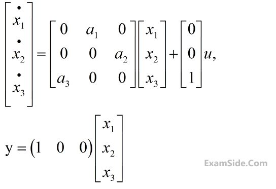
The state variable description of an LTI system is given by


where y is the output and u is input. The system is controllable for
4
GATE ECE 2011
MCQ (Single Correct Answer)
+2
-0.6
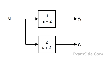
The block diagram of a system with one input u and two outputs y1 and y2 is given below


A state space model of the above system in terms of the state vector $$\underline x $$ and the output vector $$\underline y = {\left[ {\matrix{ {{y_1}} & {{y_2}} \cr } } \right]^\tau }$$ is
Questions Asked from State Space Analysis (Marks 2)
Number in Brackets after Paper Indicates No. of Questions
GATE ECE 2025 (1)
GATE ECE 2024 (1)
GATE ECE 2018 (1)
GATE ECE 2017 Set 2 (1)
GATE ECE 2016 Set 3 (1)
GATE ECE 2015 Set 2 (1)
GATE ECE 2015 Set 3 (1)
GATE ECE 2014 Set 1 (1)
GATE ECE 2014 Set 4 (1)
GATE ECE 2014 Set 3 (1)
GATE ECE 2014 Set 2 (2)
GATE ECE 2013 (2)
GATE ECE 2012 (1)
GATE ECE 2011 (1)
GATE ECE 2010 (2)
GATE ECE 2008 (1)
GATE ECE 2007 (3)
GATE ECE 2006 (1)
GATE ECE 2004 (3)
GATE ECE 2003 (1)
GATE ECE 1999 (1)
GATE ECE 1997 (1)
GATE ECE 1992 (1)
GATE ECE 1991 (1)
GATE ECE Subjects
Signals and Systems
Representation of Continuous Time Signal Fourier Series Discrete Time Signal Fourier Series Fourier Transform Discrete Time Signal Z Transform Continuous Time Linear Invariant System Transmission of Signal Through Continuous Time LTI Systems Discrete Time Linear Time Invariant Systems Sampling Continuous Time Signal Laplace Transform Discrete Fourier Transform and Fast Fourier Transform Transmission of Signal Through Discrete Time Lti Systems Miscellaneous Fourier Transform
Network Theory
Control Systems
Digital Circuits
General Aptitude
Electronic Devices and VLSI
Analog Circuits
Engineering Mathematics
Microprocessors
Communications
Electromagnetics