1
GATE ECE 2008
MCQ (Single Correct Answer)
+2
-0.6
For the circuit shown in the following figure $${I_0}$$ - $${I_3}$$ are inputs to the 4:1 multiplexer R(MSB) and S are control bits. tHE OUTPUT Zcan be represented by

2
GATE ECE 2007
MCQ (Single Correct Answer)
+2
-0.6
In the following circuit, X is given by

3
GATE ECE 2004
MCQ (Single Correct Answer)
+2
-0.6
The minimum number of 2 to 1 multiplexers required to realize a 4 to 1 mutliplexer is
4
GATE ECE 2003
MCQ (Single Correct Answer)
+2
-0.6
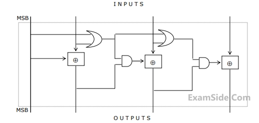
The circuit shown in figure converts
GATE ECE Subjects
Browse all chapters by subject
Network Theory
Control Systems
Electronic Devices and VLSI
Analog Circuits
Digital Circuits
Microprocessors
Signals and Systems
Representation of Continuous Time Signal Fourier Series Fourier Transform Continuous Time Signal Laplace Transform Discrete Time Signal Fourier Series Fourier Transform Discrete Fourier Transform and Fast Fourier Transform Discrete Time Signal Z Transform Continuous Time Linear Invariant System Discrete Time Linear Time Invariant Systems Transmission of Signal Through Continuous Time LTI Systems Sampling Transmission of Signal Through Discrete Time Lti Systems Miscellaneous
Communications
Electromagnetics
General Aptitude