1
GATE ECE 2003
MCQ (Single Correct Answer)
+2
-0.6
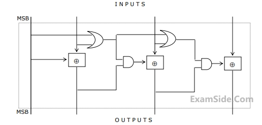
The circuit shown in figure converts
2
GATE ECE 2003
MCQ (Single Correct Answer)
+2
-0.6
The circuit shown in figure has 4 boxes each described by inputs P, Q, R and outputs Y, Z with
Y = $$\,P \oplus \,Q\, \oplus \,R$$
z= $$RQ + \overline P R\, + Q\,\overline P $$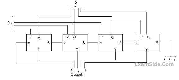 The circuit acts as a
Y = $$\,P \oplus \,Q\, \oplus \,R$$
z= $$RQ + \overline P R\, + Q\,\overline P $$
The circuit acts as a
3
GATE ECE 2001
MCQ (Single Correct Answer)
+2
-0.6
In the TTL circuit in Figure 2.11, $${S_0}$$ to $${S_0}$$ are select lines and $${X_7}$$ and $${X_0}$$are input lines. $${S_0}$$ and $${X_0}$$ are LSB'.
The output Y is

4
GATE ECE 1999
MCQ (Single Correct Answer)
+2
-0.6
For a binary half-sub-tractor having two inputs A and B, the correct set of logical expressions for the outputs
D (=A minus B) and X (=borrow) are
GATE ECE Subjects
Browse all chapters by subject
Control Systems
Engineering Mathematics
Analog Circuits
Network Theory
Electromagnetics
Electronic Devices and VLSI
Digital Circuits
Microprocessors
Signals and Systems
Discrete Fourier Transform and Fast Fourier Transform Discrete Time Signal Fourier Series Fourier Transform Continuous Time Signal Laplace Transform Fourier Transform Representation of Continuous Time Signal Fourier Series Transmission of Signal Through Continuous Time LTI Systems Miscellaneous Sampling Continuous Time Linear Invariant System Discrete Time Linear Time Invariant Systems Discrete Time Signal Z Transform Transmission of Signal Through Discrete Time Lti Systems
Communications
General Aptitude