1
GATE ECE 2010
MCQ (Single Correct Answer)
+1
-0.3
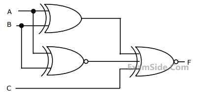
For the output F to be 1 in the logic circuit shown, the input combination should be
2
GATE ECE 2010
MCQ (Single Correct Answer)
+1
-0.3
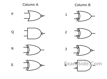
Match the logic gates in column A with their equivalents in column B.
3
GATE ECE 2002
MCQ (Single Correct Answer)
+1
-0.3
If the input to the digital circuit (in the figure) consisting of a cascade of 20 XOR-gates is X then the output Y is equal to

4
GATE ECE 2001
MCQ (Single Correct Answer)
+1
-0.3
For the ring oscillator shown in the figure, the propagation delay of each inverter is 100 pico sec. What is the fundamental frequency of the oscillator output?

GATE ECE Subjects
Browse all chapters by subject
Network Theory
Control Systems
Electronic Devices and VLSI
Analog Circuits
Digital Circuits
Microprocessors
Signals and Systems
Representation of Continuous Time Signal Fourier Series Fourier Transform Continuous Time Signal Laplace Transform Discrete Time Signal Fourier Series Fourier Transform Discrete Fourier Transform and Fast Fourier Transform Discrete Time Signal Z Transform Continuous Time Linear Invariant System Discrete Time Linear Time Invariant Systems Transmission of Signal Through Continuous Time LTI Systems Sampling Transmission of Signal Through Discrete Time Lti Systems Miscellaneous
Communications
Electromagnetics
General Aptitude