1
GATE ECE 2006
MCQ (Single Correct Answer)
+2
-0.6
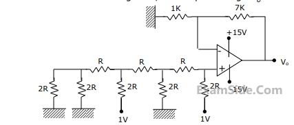
A 4-bit D/A converter is connected to a free-running 3-bit UP counter, as shown in the following figure. Which of the following waveforms will be observed at V0=?

In the figure shown above, the ground has been shown by the symbol $$\nabla $$
A

B

C

D

2
GATE ECE 2003
MCQ (Single Correct Answer)
+2
-0.6
The circuit shown in figure is a 4-bit DAC
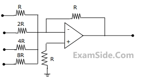 The input bits 0 and 1 are represented by 0 and 5 V respectively. The OP- AMP is ideal, but all the resistances and the 5V inputs have a tolerance of ±10%.
The specification (rounded to the nearest multiple of 5%) for the tolerance of the DAC is
The input bits 0 and 1 are represented by 0 and 5 V respectively. The OP- AMP is ideal, but all the resistances and the 5V inputs have a tolerance of ±10%.
The specification (rounded to the nearest multiple of 5%) for the tolerance of the DAC is
3
GATE ECE 2000
MCQ (Single Correct Answer)
+2
-0.6
For the 4 bit DAC shown in Figure, the output voltage $${V_0}$$ is
GATE ECE Subjects
Browse all chapters by subject
Network Theory
Control Systems
Electronic Devices and VLSI
Analog Circuits
Digital Circuits
Microprocessors
Signals and Systems
Discrete Fourier Transform and Fast Fourier Transform Discrete Time Signal Fourier Series Fourier Transform Continuous Time Signal Laplace Transform Fourier Transform Representation of Continuous Time Signal Fourier Series Transmission of Signal Through Continuous Time LTI Systems Miscellaneous Sampling Continuous Time Linear Invariant System Discrete Time Linear Time Invariant Systems Discrete Time Signal Z Transform Transmission of Signal Through Discrete Time Lti Systems
Communications
Electromagnetics
General Aptitude