1
GATE ECE 2000
MCQ (Single Correct Answer)
+1
-0.3
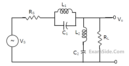
The circuit of Fig. represents a
2
GATE ECE 1998
MCQ (Single Correct Answer)
+1
-0.3
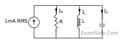
The parallel $$RLC$$ circuit shown in figure is in resonance. In this circuit
3
GATE ECE 1996
MCQ (Single Correct Answer)
+1
-0.3
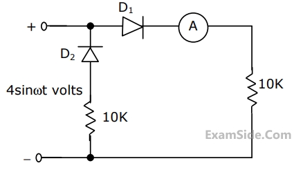
In the circuit of Fig., assume that the diodes are ideal and the meter is an average indicating ammeter. The ammeter will read
4
GATE ECE 1996
MCQ (Single Correct Answer)
+1
-0.3
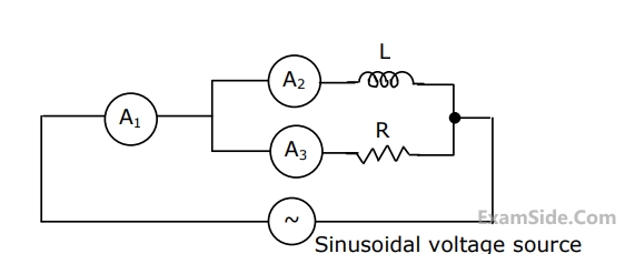
In Fig., A1, A2 and A3 are ideal ammeters. If A2 and A3 read 3 A and 4 A respectively, then A1 should read
GATE ECE Subjects
Browse all chapters by subject
General Aptitude
Network Theory
Microprocessors
Signals and Systems
Discrete Fourier Transform and Fast Fourier Transform Discrete Time Signal Fourier Series Fourier Transform Continuous Time Signal Laplace Transform Fourier Transform Representation of Continuous Time Signal Fourier Series Transmission of Signal Through Continuous Time LTI Systems Miscellaneous Sampling Continuous Time Linear Invariant System Discrete Time Linear Time Invariant Systems Discrete Time Signal Z Transform Transmission of Signal Through Discrete Time Lti Systems
Electromagnetics
Digital Circuits
Electronic Devices and VLSI
Control Systems
Communications
Engineering Mathematics