For the circuit shown, the locus of the impedance Z(j$$\omega$$) is plotted as $$\omega$$ increases from zero to infinity. The values of R1 and R2 are :
A
R1 = 2 k$$\Omega$$, R2 = 3 k$$\Omega$$
B
R1 = 5 k$$\Omega$$, R2 = 2 k$$\Omega$$
C
R1 = 5 k$$\Omega$$, R2 = 2.5 k$$\Omega$$
D
R1 = 2 k$$\Omega$$, R2 = 5 k$$\Omega$$
2
GATE ECE 2022
MCQ (Single Correct Answer)
+2
-0.67
Consider the circuit shown in the figure with input V(t) in volts. The sinusoidal steady state current I(t) flowing through the circuit is shown graphically (where t is in seconds). The circuit element Z can be _________.
A
a capacitor of 1 F
B
an inductor of 1 H
C
a capacitor of $$\sqrt 3 $$F
D
an inductor of $$\sqrt 3 $$H
3
GATE ECE 2020
MCQ (Single Correct Answer)
+2
-0.67
$$ \text { The current } I \text { in the given network is } $$
A
$2.38 \angle-96.37^{\circ} \mathrm{A}$.
B
0 A .
C
$2.38 \angle-23.63^{\circ} \mathrm{A}$.
D
$2.38 \angle 143.63^{\circ} \mathrm{A}$.
4
GATE ECE 2018
MCQ (Single Correct Answer)
+2
-0.67
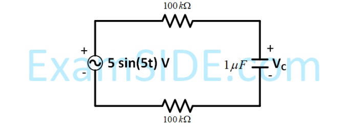
For the circuit given in the figure, the voltage
VC
(in volts) across the capacitor is :