1
GATE ECE 2000
MCQ (Single Correct Answer)
+2
-0.6
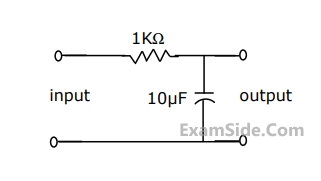
In Fig., the steady state output voltage corresponding to the input voltage $$\left( {3 + 4\sin \,\,100\,t} \right)$$ $$V$$ is
2
GATE ECE 1993
MCQ (Single Correct Answer)
+2
-0.6
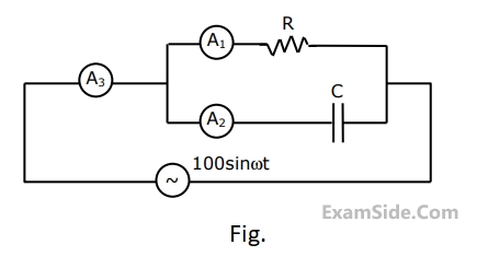
In figure, A1, A2 and A3 are ideal ammeters. If A1 reads 5 A, A2, A2 reads 12 A, then A3 should read
3
GATE ECE 1992
MCQ (Single Correct Answer)
+2
-0.6
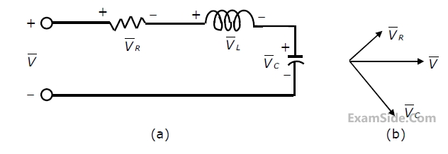
For the series R-L-C circuit of figure(a), the partial phasor diagram at a certain
frequency is shown in figure (b).The operating frequency of the circuit is:
4
GATE ECE 1991
MCQ (Single Correct Answer)
+2
-0.6
In a series RLC high Q circuit, the current peaks at a frequency
GATE ECE Subjects
Browse all chapters by subject
General Aptitude
Network Theory
Microprocessors
Signals and Systems
Discrete Time Signal Fourier Series Fourier Transform Continuous Time Signal Laplace Transform Fourier Transform Discrete Fourier Transform and Fast Fourier Transform Representation of Continuous Time Signal Fourier Series Discrete Time Linear Time Invariant Systems Transmission of Signal Through Continuous Time LTI Systems Transmission of Signal Through Discrete Time Lti Systems Miscellaneous Continuous Time Linear Invariant System Discrete Time Signal Z Transform Sampling
Electromagnetics
Digital Circuits
Electronic Devices and VLSI
Control Systems
Communications
Engineering Mathematics