1
GATE ECE 2014 Set 1
MCQ (Single Correct Answer)
+2
-0.6
The output F in the digital logic circuit shown in the figure is

2
GATE ECE 2008
MCQ (Single Correct Answer)
+2
-0.6
Which of the follwing Boolean expression correctly represents the relation between P, Q, R and M1?

3
GATE ECE 2002
MCQ (Single Correct Answer)
+2
-0.6
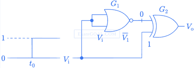
The gates G1 and G2 in figure have propagation delays of 10nsec and 20nsec respectively. If the input Vi makes an abrupt change from logic 0 to 1 at
time t = t0, then the output waveform V0 is
A

B

C

D

4
GATE ECE 2001
MCQ (Single Correct Answer)
+2
-0.6
In the figure the LED

GATE ECE Subjects
Browse all chapters by subject
General Aptitude
Network Theory
Microprocessors
Signals and Systems
Discrete Time Signal Fourier Series Fourier Transform Continuous Time Signal Laplace Transform Fourier Transform Discrete Fourier Transform and Fast Fourier Transform Representation of Continuous Time Signal Fourier Series Discrete Time Linear Time Invariant Systems Transmission of Signal Through Continuous Time LTI Systems Transmission of Signal Through Discrete Time Lti Systems Miscellaneous Continuous Time Linear Invariant System Discrete Time Signal Z Transform Sampling
Electromagnetics
Digital Circuits
Electronic Devices and VLSI
Control Systems
Communications
Engineering Mathematics