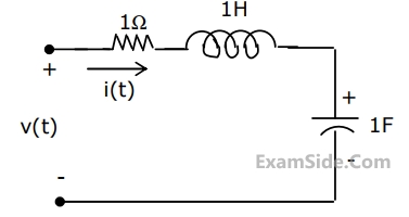
The circuit shown in Fig, has initial current $${\mathrm i}_\mathrm L\left(0^-\right)\;=\;1\;\mathrm A$$ through the inductor and an initial voltage $${\mathrm v}_\mathrm C\left(0^-\right)\;=\;-1\;\mathrm V$$ across the capacitor. For input v(t) = u(t), the Laplace transform of the current i(t) for t ≥ 0 is
The circuit is given in figure.Assume that the switch S is in position 1 for a long time and thrown to position 2 at t = 0.
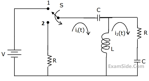
I1(s) and I2(s) are the Laplace transforms of i1(t) and i2(t) respectively. The equations for the loop currents I1(s) and I2(s) for the circuit shown in figure, after the switch is brought from position 1 to position 2 at t = 0, are


The circuit is given in figure.Assume that the switch S is in position 1 for a long time and thrown to position 2 at t = 0.
At t = 0+, the current i1 is
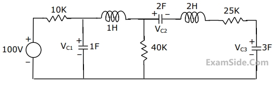
The voltage VC1, VC2 and VC3 across the capacitors in the circuit in Fig., under steady state, are respectively
GATE ECE Subjects
Browse all chapters by subject