1
GATE ECE 2015 Set 2
Numerical
+2
-0
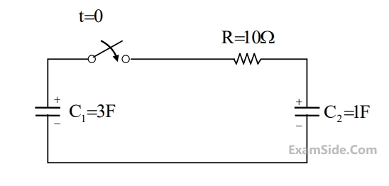
In the circuit shown, the initial voltages across the capacitors
C1 and C2
are 1 V and 3 V,
respectively. The switch is closed at time t = 0. The total energy dissipated (in Joules) in the
resistor R until steady state is reached is _______________.
Your input ____
2
GATE ECE 2014 Set 4
Numerical
+2
-0
In the circuit shown in the figure, the value of V0(t) (in Volts) for $$t\rightarrow\infty$$ is ______.
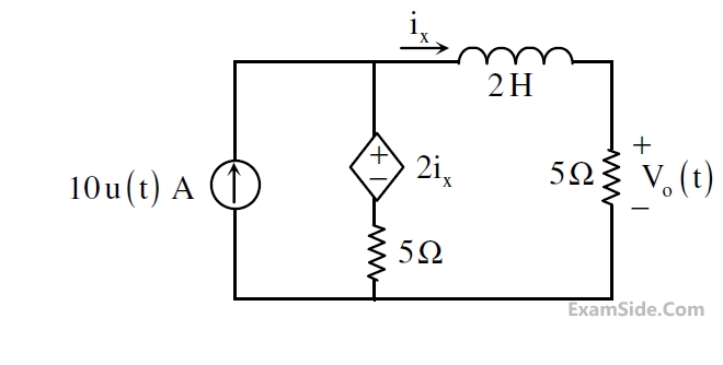
Your input ____
3
GATE ECE 2014 Set 2
MCQ (Single Correct Answer)
+2
-0.6
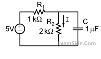
In the figure shown, the capacitor is initially uncharged. Which one of the following
expressions describes the current I(t) (in mA) for t > 0?
4
GATE ECE 2011
MCQ (Single Correct Answer)
+2
-0.6
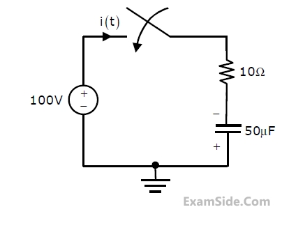
In the circuit shown below, the initial charge on the capacitor is 2.5 mC, with the voltage polarity as indicated. The switch is closed at time t=0. The current i(t) at a time t after the switch is closed is
GATE ECE Subjects
Browse all chapters by subject
General Aptitude
Network Theory
Microprocessors
Signals and Systems
Discrete Fourier Transform and Fast Fourier Transform Discrete Time Signal Fourier Series Fourier Transform Continuous Time Signal Laplace Transform Fourier Transform Representation of Continuous Time Signal Fourier Series Transmission of Signal Through Continuous Time LTI Systems Miscellaneous Sampling Continuous Time Linear Invariant System Discrete Time Linear Time Invariant Systems Discrete Time Signal Z Transform Transmission of Signal Through Discrete Time Lti Systems
Electromagnetics
Digital Circuits
Electronic Devices and VLSI
Control Systems
Communications
Engineering Mathematics