1
GATE ECE 2003
MCQ (Single Correct Answer)
+2
-0.6
The circuit is given in figure.Assume that the switch S is in position 1 for a long time and thrown to position 2 at t = 0.
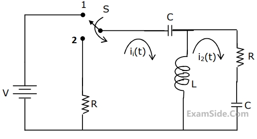
At t = 0+, the current i1 is
2
GATE ECE 1996
MCQ (Single Correct Answer)
+2
-0.6
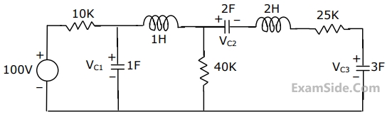
The voltage VC1, VC2 and VC3 across the capacitors in the circuit in Fig., under steady state, are respectively
3
GATE ECE 1992
MCQ (Single Correct Answer)
+2
-0.6
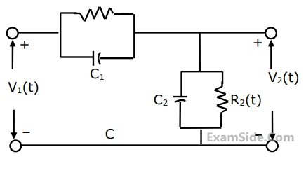
For the compensated attenuator of figure, the impulse response under the condition $$R_1C_1\;=\;R_2C_2$$ is:
4
GATE ECE 1990
MCQ (Single Correct Answer)
+2
-0.6
If the Laplace transform of the voltage across a capacitor of value of $$\frac12\;\mathrm F$$ is $$V_C\;\left(s\right)\;=\;\frac{s\;+\;1}{s^3\;+\;s^2\;+\;s\;+\;1}$$ , the value of the current through the capacitor at t = 0+ is
GATE ECE Subjects
Browse all chapters by subject
Network Theory
Control Systems
Electronic Devices and VLSI
Analog Circuits
Digital Circuits
Microprocessors
Signals and Systems
Discrete Fourier Transform and Fast Fourier Transform Discrete Time Signal Fourier Series Fourier Transform Continuous Time Signal Laplace Transform Fourier Transform Representation of Continuous Time Signal Fourier Series Transmission of Signal Through Continuous Time LTI Systems Miscellaneous Sampling Continuous Time Linear Invariant System Discrete Time Linear Time Invariant Systems Discrete Time Signal Z Transform Transmission of Signal Through Discrete Time Lti Systems
Communications
Electromagnetics
General Aptitude