1
GATE ECE 2017 Set 1
Numerical
+2
-0
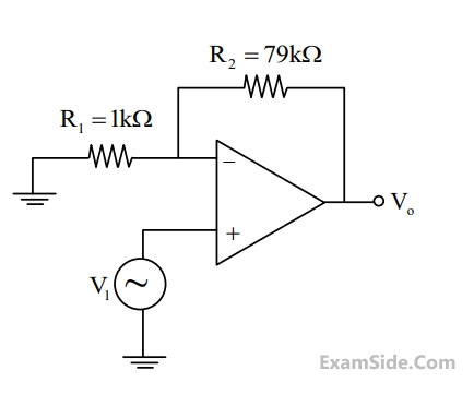
The amplifier circuit shown in the figure is
implemented using a compensated operational
amplifier (op-amp), and has an open-loop voltage
gain, A0 105 V/V and an open-loop cut-off frequency, fC = 8 Hz. The voltage gain of the amplifier
at 15 kHz, in V/V, is __________.
Your input ____
2
GATE ECE 2016 Set 2
Numerical
+2
-0
An opamp has a finite open loop voltage gain of 100. Its input offset voltage Vios (= +5mV) is
modeled as shown in the circuit below. The amplifier is ideal in all other respects. Vinput is 25 mV.

The output voltage (in millivolts) is ________.
Your input ____
3
GATE ECE 2016 Set 2
Numerical
+2
-0
In the opamp circuit shown, the Zener diodes Z1 and Z2 clamp the output voltage Vo to +5 V or -5 V. The switch S is intially closed and is opened at time t = 0

The time t = t1 (in seconds) at which Vo changes state is _____.
Your input ____
4
GATE ECE 2016 Set 1
Numerical
+2
-0
A p-i-n photo diode of responsivity 0.8A/W is connected to the inverting input of an ideal opamp as shown in the figure, +VCC = 15V, - VCC = -15V, Load resistor RL = 10 k$$\Omega $$ . If 10$$\mu $$W of power is incident on the photodiode, then the value of the photocurrent (in $$\mu $$A) through the load is _____.

Your input ____
GATE ECE Subjects
Browse all chapters by subject
General Aptitude
Network Theory
Microprocessors
Signals and Systems
Discrete Fourier Transform and Fast Fourier Transform Discrete Time Signal Fourier Series Fourier Transform Continuous Time Signal Laplace Transform Fourier Transform Representation of Continuous Time Signal Fourier Series Transmission of Signal Through Continuous Time LTI Systems Miscellaneous Sampling Continuous Time Linear Invariant System Discrete Time Linear Time Invariant Systems Discrete Time Signal Z Transform Transmission of Signal Through Discrete Time Lti Systems
Electromagnetics
Digital Circuits
Electronic Devices and VLSI
Control Systems
Communications
Engineering Mathematics