1
GATE ECE 2003
MCQ (Single Correct Answer)
+2
-0.6
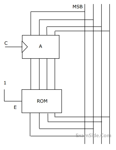
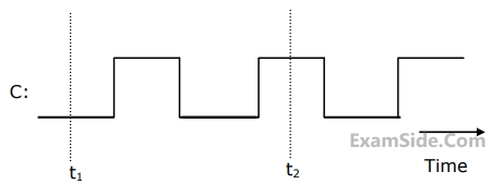
In the circuit shown in Figure, A is a parallel in, parallel-out 4-bit register, which loads at the rising edge of the clock C. The input lines are connected to a 4-bit bus, W. Its output acts as the input to a 16×4 ROM whose output is floating when
the enable input E is 0. A partial table of the contents of the ROM is as follows


The clock to the register is shown, and the data on the W bus at time t$$_1$$ is 0110. The data on the bus at time t$$_2$$ is


2
GATE ECE 2002
MCQ (Single Correct Answer)
+2
-0.6
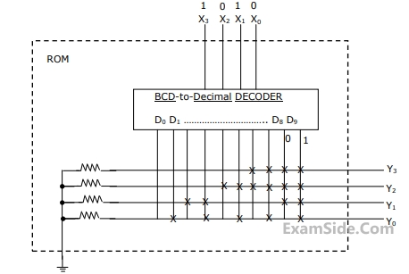
If the input X$$_3$$, X$$_2$$, X$$_1$$, X$$_0$$ to the ROM in figure 2.12 are 8-4-2-1 BCD numbers, then the outpus are Y$$_3$$,Y$$_2$$, Y$$_1$$, Y$$_0$$ are


Questions Asked from Semiconductor Memories (Marks 2)
Number in Brackets after Paper Indicates No. of Questions
GATE ECE Subjects
Signals and Systems
Representation of Continuous Time Signal Fourier Series Fourier Transform Continuous Time Signal Laplace Transform Discrete Time Signal Fourier Series Fourier Transform Discrete Fourier Transform and Fast Fourier Transform Discrete Time Signal Z Transform Continuous Time Linear Invariant System Discrete Time Linear Time Invariant Systems Transmission of Signal Through Continuous Time LTI Systems Sampling Transmission of Signal Through Discrete Time Lti Systems Miscellaneous
Network Theory
Control Systems
Digital Circuits
General Aptitude
Electronic Devices and VLSI
Analog Circuits
Engineering Mathematics
Microprocessors
Communications
Electromagnetics