1
GATE ECE 2000
Subjective
+5
-0
The operating conditions (ON = 1, OFF = 0) of three pumps (x,y,z) are to be
monitored. x = 1 implies that pump X is on. It is required that the indicator (LED)
on the panel should glow when a majority of the pumps fail.


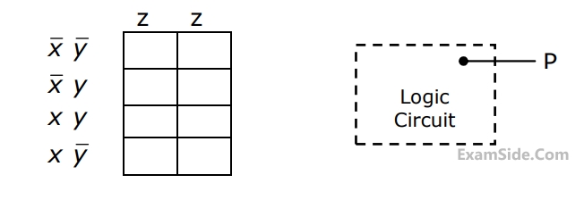
(a) Enter the logical values in the K-map in the format shown in figure 3(a). Derive
the minimal Boolean sum-of-products expression whose output is zero when a majority of the pumps fail.
(b) The above expression is implemented using logic gates, and point P is the
output of this circuit, as shown in figure 3(b). P is at 0 V when a majority of the pumps fails and is at 5 V otherwise. Design a circuit to drive the LED using this output. The current through the LED should be 10 mA and the voltage drop across it is 1V. Assume that P can source or sink 10 mA and a 5 V supply is available.
2
GATE ECE 1993
Subjective
+5
-0
The truth table for the output Y in terms of three inputs A, B and C are given in
table. Draw a logic circuit realization using only NOR gates.


Questions Asked from Logic Gates (Marks 5)
Number in Brackets after Paper Indicates No. of Questions
GATE ECE Subjects
Signals and Systems
Representation of Continuous Time Signal Fourier Series Fourier Transform Continuous Time Signal Laplace Transform Discrete Time Signal Fourier Series Fourier Transform Discrete Fourier Transform and Fast Fourier Transform Discrete Time Signal Z Transform Continuous Time Linear Invariant System Discrete Time Linear Time Invariant Systems Transmission of Signal Through Continuous Time LTI Systems Sampling Transmission of Signal Through Discrete Time Lti Systems Miscellaneous
Network Theory
Control Systems
Digital Circuits
General Aptitude
Electronic Devices and VLSI
Analog Circuits
Engineering Mathematics
Microprocessors
Communications
Electromagnetics