Consider the circuit shown in the figure with input V(t) in volts. The sinusoidal steady state current I(t) flowing through the circuit is shown graphically (where t is in seconds). The circuit element Z can be _________.
A
a capacitor of 1 F
B
an inductor of 1 H
C
a capacitor of $$\sqrt 3 $$F
D
an inductor of $$\sqrt 3 $$H
2
GATE ECE 2020
MCQ (Single Correct Answer)
+2
-0.67
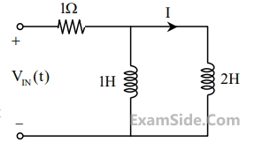
$$ \text { The current } I \text { in the given network is } $$
A
$2.38 \angle-96.37^{\circ} \mathrm{A}$.
B
0 A .
C
$2.38 \angle-23.63^{\circ} \mathrm{A}$.
D
$2.38 \angle 143.63^{\circ} \mathrm{A}$.
3
GATE ECE 2018
MCQ (Single Correct Answer)
+2
-0.67
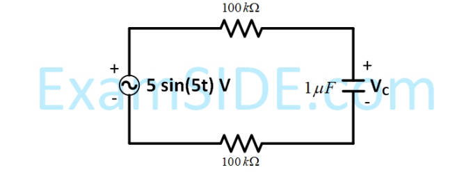
For the circuit given in the figure, the voltage
VC
(in volts) across the capacitor is :
A
1.25$$\sqrt 2 $$ sin(5t - 0.25$$\pi $$)
B
1.25$$\sqrt 2 $$ sin(5t - 0.125$$\pi $$)
C
2.5$$\sqrt 2 $$ sin(5t - 0.25$$\pi $$)
D
2.5$$\sqrt 2 $$ sin(5t - 0.125$$\pi $$)
4
GATE ECE 2017 Set 1
Numerical
+2
-0
In the circuit shown the voltage $${V_{IN}}\,\left( t \right)$$ is described by:
$$${V_{IN}}\,\left( t \right) = \left\{ {\matrix{
{0,} & {for\,\,\,t < 0} \cr
{15Volts,} & {for\,\,\,t \ge 0} \cr
} } \right.$$$
where $$'t'$$ is in seconds. The time (in seconds) at which the current $${\rm I}$$ in the circuit will reach the value $$2$$ Ampere is ______ .