1
GATE ECE 2021
MCQ (Single Correct Answer)
+1
-0.33
In the circuit shown in the figure, the transistors $M_1$ and $M_2$ are operating in saturation. The channel length
modulation coefficients of both the transistors are non-zero. The transconductance of the MOSFETs $M_1$ and $M_2$ are $g_{m 1}$ and $g_{m 2}$, respectively, and the internal resistance of the MOSFETs $M_1$ and $M_2$ are $r_{01}$ and $r_{02}$ respectively.
 Ignoring the body effect, the ac small signal voltage gain ( $d V_{\text {out }} / d V_{\text {in }}$ ) of the circuit is
2
GATE ECE 1998
MCQ (Single Correct Answer)
+1
-0.3
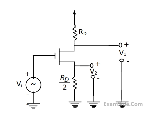
In the MOSFET amplifier of the figure the signal output V1 and V2 obey the relationship
3
GATE ECE 1995
Fill in the Blanks
+1
-0
An n-channel JFET has IDSS = 1 mA and Vp = -5 V. Its maximum transconductance is ______
4
GATE ECE 1994
Fill in the Blanks
+1
-0
The transit time of a current carriers through the channel of an FET decides its ____________characteristics.
GATE ECE Subjects
Browse all chapters by subject
Network Theory
Control Systems
Electronic Devices and VLSI
Analog Circuits
Digital Circuits
Microprocessors
Signals and Systems
Discrete Fourier Transform and Fast Fourier Transform Discrete Time Signal Fourier Series Fourier Transform Continuous Time Signal Laplace Transform Fourier Transform Representation of Continuous Time Signal Fourier Series Transmission of Signal Through Continuous Time LTI Systems Miscellaneous Sampling Continuous Time Linear Invariant System Discrete Time Linear Time Invariant Systems Discrete Time Signal Z Transform Transmission of Signal Through Discrete Time Lti Systems
Communications
Electromagnetics
General Aptitude