1
GATE ECE 2015 Set 3
Numerical
+1
-0
In the circuit shown, assume that diodes D1 and D2 are ideal. In the steady-state condition the average voltage Vab (in Volts) across the 0.5 μF capacitor is _____.

Your input ____
2
GATE ECE 2015 Set 2
MCQ (Single Correct Answer)
+1
-0.3
If the circuit shown has to function as a clamping circuit, which one of the following
conditions should be satisfied for sinusoidal signal of period T?

3
GATE ECE 2014 Set 3
Numerical
+1
-0
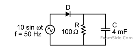
The figure shows a half-wave rectifier. The diode D is ideal. The average steady-state current
(in Amperes) through the diode is approximately ____________.
Your input ____
4
GATE ECE 2014 Set 4
MCQ (Single Correct Answer)
+1
-0.3
For a given sample-and-hold circuit, if the value of the hold capacitor is increased, then
GATE ECE Subjects
Browse all chapters by subject
Control Systems
Engineering Mathematics
Analog Circuits
Network Theory
Electromagnetics
Electronic Devices and VLSI
Digital Circuits
Microprocessors
Signals and Systems
Discrete Fourier Transform and Fast Fourier Transform Discrete Time Signal Fourier Series Fourier Transform Continuous Time Signal Laplace Transform Fourier Transform Representation of Continuous Time Signal Fourier Series Transmission of Signal Through Continuous Time LTI Systems Miscellaneous Sampling Continuous Time Linear Invariant System Discrete Time Linear Time Invariant Systems Discrete Time Signal Z Transform Transmission of Signal Through Discrete Time Lti Systems
Communications
General Aptitude