GATE ECE

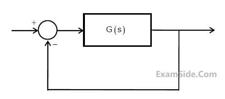
The mid-band voltage gain of the amplifier is approximately

and V is the voltage across the diode (taken as positive for forward bias). For an input voltage $${V_i}\,\, = \,\, - 1V,$$ the output voltage V0 is


A triangular wave which goes from -12V to 12V is applied to the inverting input of the OP-AMP. Assume that the output of the OP-AMP swings from +15V to -15V. The voltage at the non-inverting input switches between.
The Value of DC current IE is
The number of quantitization levels required to reduce the quantization noise by a factor of 4 would be
Assuming the signal to be uniformly distributed between its peak values, the signal to noise ratio at the quantizer output is
If the bits 0 and 1 are transmitted using bipolar pulses, the minimum bandwidth required for distortion free transmission is
 Which of the following statements is true?
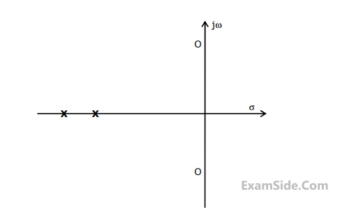
Group I $$$P=\frac{25}{s^2+25}\;\;\;\;\;Q=\frac{36}{s^2+20s+36}$$$ $$$R=\frac{36}{s^2+12s+36}\;\;\;\;\;S=\frac{49}{s^2+7s+49}$$$
Group II


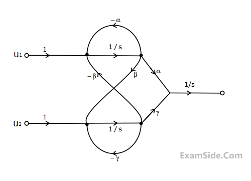
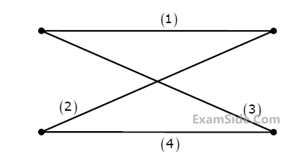
The set of equations that correspond to this signal flow graph is
The output of this system to the sinusoidal input x(t) = 2cos(t) for all time 't' is
The frequency response H(ω) of the system in terms of angular frequency 'ω' is given by h( ω)
 Group - I
Group - II
1. PID controller
2. Lead compensator
3. Lag compensator
The counter starts from the clear state.

The magnitude of the error between VDAC and Vin at steady state in volts is


Which of the following waveforms correctly represents the output at Q1?
The counter starts from the clear state.
The stable reading of the LED display is


The maximum and minimum values of the output voltage respectively are

 The current Ix is related to Ibias as
$$f(z) = {1 \over {{{\left( {z + 2} \right)}^2}{{\left( {z - 2} \right)}^2}}}$$ at z = 2 is
$$P = \left[ {\matrix{ {{p_{11}}} & {{p_{12}}} \cr {{p_{21}}} & {{p_{22}}} \cr } } \right]$$ are non-zero and one of the eigen values is zero. Which of the following statement is true?
2710 LXI H, 30A0H
DAD H
PCHL
All addresses and constants are in Hex. Let PC be the contents of the program counter and HL be the contents of the HL register pair just after executing PCHL.
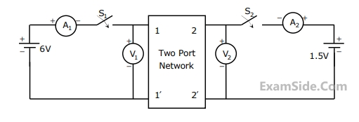
Which of the following statements is correct. (i) $${S_1} - open,\,\,\,\,{S_2} - closed$$
$${A_1} = 0\,A,\,\,\,\,\,\,{V_1} = \,4.5\,\,V,$$
$${V_2}\, = \,1.5\,V,\,\,\,\,{A_2}\, = \,1\,A$$
(ii) $${S_1} - Closed,\,\,\,\,{S_2} - Open$$
$${A_1} = 4\,A,\,\,\,\,\,\,{V_1} = \,6\,\,V,$$
$${V_2}\, = \,6\,V,\,\,\,\,{A_2}\, = \,0\,A$$
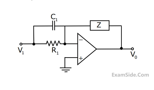
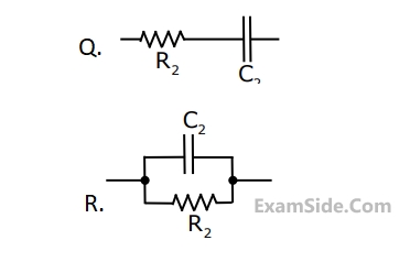
 The h-parameter matrix for this network is
 (i) $${S_1} - open,\,\,\,\,{S_2} - closed$$
$${A_1} = 0\,A,\,\,\,\,\,\,{V_1} = \,4.5\,\,V,$$
$${V_2}\, = \,1.5\,V,\,\,\,\,{A_2}\, = \,1\,A$$
(ii) $${S_1} - Closed,\,\,\,\,{S_2} - Open$$
$${A_1} = 4\,A,\,\,\,\,\,\,{V_1} = \,6\,\,V,$$
$${V_2}\, = \,6\,V,\,\,\,\,{A_2}\, = \,0\,A$$
The z-parameter matrix for this network is 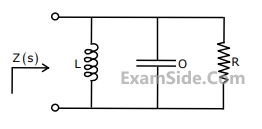
The circuit shown in the figure is used to charge the capacitor C alternately from two current sources as indicated. The switches S1 and S2 are mechanically coupled and connected as follows
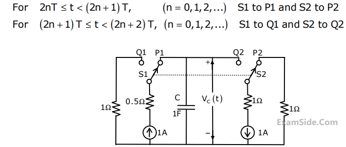
Assume that the capacitor has zero initial charge. Given that u(t) is a unit step function, the voltage Vc(t) across the capacitor is given by
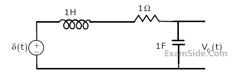 For t > 0, the output voltage Vc(t) is
For t > 0, the voltage across the resistor is
For t > 0, the output voltage Vc(t) is
For t > 0, the voltage across the resistor is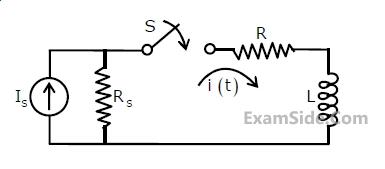

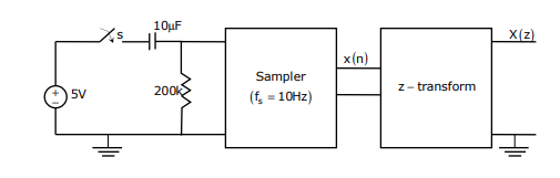
The samples x (n) (n=0, 1, 2,...........) are given by
Two of the angular frequencies at which its Fourier transform becomes zero are
y (n) = $${1 \over N}\,\sum\limits_{r = 0}^{N - 1} x \,\left( r \right)x\,(n + r\,)$$ is
Properties
P1 : Linear but NOT time-invariant
P2: Time-invariant but NOT linear
P3: Linear and time-invariant
Relations
R1: y(t) = $${t^2}$$ x(t)
R2: y(t) = t$$\left| {x(t)} \right|$$
R3: y(t) = $$\left| {x(t)} \right|$$
R4: y(t) = x(t-5)
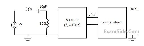
The expression and the region of convergence of the z-transform of the sampled signal are