GATE ECE 1991
GATE ECE
1
Two non-inverting amplifiers, one having a unity gain and other having a gain of twenty, are made using identical operational gain amplifier, the amplifier with gain twenty has
2
In figure, all transistors are identical and have a high value of beta. The voltage
VDC is equal to ______.

3
Two resistors $$\,{R_1}$$ and $$\,{R_2}$$ (in ohms) at temperatures $${T_1}{}^ \circ K$$ and $${T_2}{}^ \circ K$$ respectively, are connected in series. Their equivalent noise temperature is.
4
For the signal constellation shown in the figure, the type of modulation is ________.

5
A binary source has symbol probabilities 0.8 and 0.2. If extension coding (blocks of 4 symbols) is used, the lower and upper bounds on the average code word length are :
(a)lower___________.
(b) higher_________.
(a)lower___________.
(b) higher_________.
6
A linear second order single input continuous-time system is described by the
following set of differential equations
$$$\eqalign{
& \mathop {{x_1}}\limits^ \bullet \left( t \right) = - 2{x_1}\left( t \right) + 4{x_2}\left( t \right) \cr
& \mathop {{x_1}}\limits^ \bullet \left( t \right) = 2{x_1}\left( t \right) - {x_2}\left( t \right) + u\left( t \right) \cr} $$$
Where x1(t) and x2(t) are the state variables and u (t) is the control variable. The system is
Where x1(t) and x2(t) are the state variables and u (t) is the control variable. The system is
7
The open-loop transfer function of a feedback control system is
G(s)=$${1 \over {{{\left( {s + 1} \right)}^3}}}$$
The gain margin of the system is
The gain margin of the system is
8
The characteristic equation of a feedback control system is given by
s3 +5s2 +(K + 6)s + K =0
Where K > 0 is a scalar variable parameter. In the root loci diagram of the system the asymptotes of the root locus for large values of K meet at a point in the s-plane whose coordinates are
s3 +5s2 +(K + 6)s + K =0
Where K > 0 is a scalar variable parameter. In the root loci diagram of the system the asymptotes of the root locus for large values of K meet at a point in the s-plane whose coordinates are
9
A second order system has a transfer function given by $$\mathrm G\left(\mathrm s\right)\;=\;\frac{25}{\mathrm s^2\;+\;8\mathrm s\;+\;25}$$ .If the system, initially at rest is subjected to a unit step input at t = 0, the
second peak in response will occur at
10
In the signal flow graph of Figure, the gain c/r will be

11
A unity feedback control system has the open loop transfer function
$$G\left(s\right)\;=\;\frac{4\left(1\;+\;2s\right)}{s^2\left(s\;+\;2\right)}$$ .If the input to the system is a unit ramp, the steady-state error will be
12
The CMOS equivalent of the following n MOS gate (figure) is ________ (draw the circuit ).

13
A SR FLIP-FLOP can be converted into a T FLIP-FLOP by connecting ___ to Q and ___ to $$\overline Q $$.
14
In figure, the Boolean expression for the output in terms of inputs A, B and C when the clock ‘CK’ is high, is given by _______.

15
The four variable function f is given in terms of min-terms as:
f (A B C D ) = $$\sum {} $$m (2,3,8,10,11,12,14,15 .)
Using the K-map minimize the function in the sum of products form. Also, given the realization using only two-input NAND gates
.
16
The electric field component of a uniform plane electromagnetic wave propagating in the $$Y$$-direction in a lossless medium will satisfy the equation
17
The input impedance of a short-circuited lossless transmission line guarter wave long is
18
A uniform plane electromagnetic wave traveling in free-space enters into a lossless medium at normal incidence. In the medium its velocity reduces by 50% and in free space sets up a standing wave having a reflection coefficient of - 0.125. Calculate the permeability and the permittivity of the medium.
19
In a board side array of 20 isotropic radiators, equally spaced at a distance of $$\lambda /2$$, the veam width between first nulls is
20
In the radiation pattern of a 3-element array of isotropic radiators equally spaced at distances of $${\lambda /4}$$ it is required to place a null at an angle of 33.56 degrees off the end-fire direction. Calculate the progressive phase shifts to be applied to the elements. Also calculate the angle at which the main beam is placed for this phase distribution.
21
The small signal capacitances of an abrupt P+−N junction is 1 nF at zero
bias. If the built-in voltage is 1 volt, the capacitance at a reverse bias voltage of
99 volts is equal to
22
Referring to the figure. The switch S is in position 1 initially and steady state
conditions exist from time t = 0 to t = t0. At t = t0, the switch is suddenly thrown into
position 2. The current I through the 10K resistor as a function of time t, from t =
0 is (in mA) _____________.

(Give the sketch showing the magnitudes of the current at t = 0, t = t0 and t = $$\infty$$ )
23
A silicon sample is uniformly doped with 1016 phosphorous atoms/cm3 and 2 ×10¹⁶ boron atoms/cm3. If all the dopants are fully ionized, the material is
24
The program given below is run on an 8085 based microcomputer system. Determine the contents of the registers: PC, SP, B,
C, H, L after a half instruction is executed.
LOC
2000 START: LXI SP, 1000H
LXI H, 2F37 H
XRA A
MOV A, H
INX H
PUSH H
CZ 20 FF H JMP 3000 H
HLT
20FF ADD H
RZ
POP B
PUSH B
RNZ
HLT
LOC
2000 START: LXI SP, 1000H
LXI H, 2F37 H
XRA A
MOV A, H
INX H
PUSH H
CZ 20 FF H JMP 3000 H
HLT
20FF ADD H
RZ
POP B
PUSH B
RNZ
HLT
25
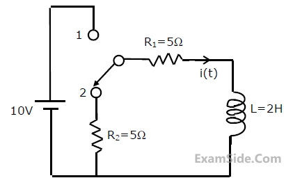
The network shown in figure is
initially under steady-state
condition with the switch in
position 1. The switch is moved
from position 1 to position 2 at t =
0. Calculate the current
i(t) through R1 after switching.
26
Two two-port networks are connected in cascade. The combination is to be
represented as a single two-port network. The parameters of the network are
obtained by multiplying the individual
27
The necessary and sufficient condition for a rational function of s, T(s) to be
driving point impedance of an RC network is that all poles and zeros should be
28
In a series RLC high Q circuit, the current peaks at a frequency
29
The voltage across an impedance in a network is V(s) = Z(s) I(s), where V(s), Z(s) and $${\rm I}$$(s) are the Laplace Transforms of the corresponding time functions V(t), z(t) and i(t).
The voltage v(t) is
30
An excitation is applied to a system at $$t = T$$ and its response is zero for $$ - \infty < t < T$$.
Such a system is a
31
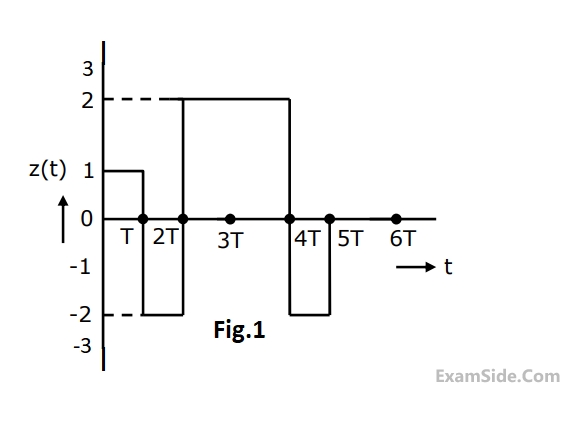
Find the Laplace transform of the waveform x(t) shown in Fig.1.
32
A signal has frequency components from 300 Hz to 1.8 KHz. The minimum possible rate at which the signal has to be sampled is ______ (fill in the blank).
33
The pole-zero pattern of a certain filter is shown in the Fig. The filter must be of the following type.
