GATE ECE

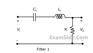
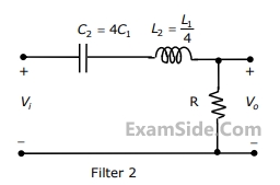
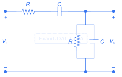
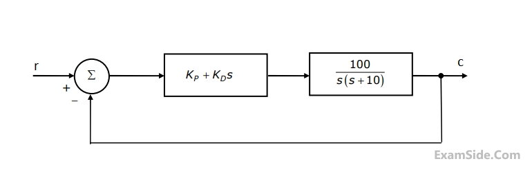
The transfer function $${V_o}\left( s \right)/{V_i}\left( s \right)$$ is

If $${V_i} = {V_1}\,\,\sin \left( {\omega \tau + \phi } \right),$$ then the minimum and maximum values of $$\phi $$ (in radians) are respectively


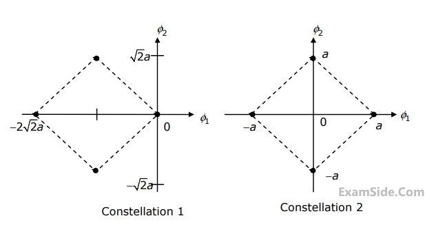
The ratio of the average energy of Constellation 1 to the average energy of Constellation 2 is
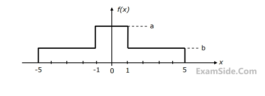
The values of a and b are
If these constellations are used for digital communications over an AWGN channel, then which of the following statements is true?
Assuming that the reconstruction levels of the quantizer are the mid-points of the decision boundaries, the ratio of signal power to quantization noise power is

If the initial state vector of the system is $$x\left( 0 \right) = \left[ {\matrix{ 1 \cr { - 2} \cr } } \right],$$
then the system response is $$x\left( t \right) = \left[ {\matrix{ {{e^{ - 2t}}} \cr { - 2{e^{ - 2t}}} \cr } } \right].$$
If the initial state vector of the system changes to $$x\left( 0 \right) = \left[ {\matrix{ 1 \cr { - 1} \cr } } \right],$$
then the system response becomes $$x\left( t \right) = \left[ {\matrix{ {{e^{ - t}}} \cr { - {e^{ - t}}} \cr } } \right].$$
The system matrix a is
If the initial state vector of the system is $$x\left( 0 \right) = \left[ {\matrix{ 1 \cr { - 2} \cr } } \right],$$
then the system response is $$x\left( t \right) = \left[ {\matrix{ {{e^{ - 2t}}} \cr { - 2{e^{ - 2t}}} \cr } } \right].$$
If the initial state vector of the system changes to $$x\left( 0 \right) = \left[ {\matrix{ 1 \cr { - 1} \cr } } \right],$$
then the system response becomes $$x\left( t \right) = \left[ {\matrix{ {{e^{ - t}}} \cr { - {e^{ - t}}} \cr } } \right].$$
The eigen value and eigen vector pairs $$\left( {{\lambda _{i,}}{V_i}} \right)$$ for the system are
Where 'ω' is the speed of the motor, 'ia' is the armature current and u is the armature voltage. The transfer function $${{\omega \left( s \right)} \over {U\left( s \right)}}$$ of the motor is

$${V_{R\,}}\, = \,10V$$ and $$R\, = \,10k\Omega $$

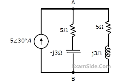
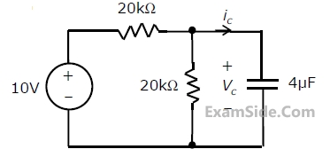
The current i is


$${V_{R\,}}\, = \,10V$$ and $$R\, = \,10k\Omega $$
The voltage V0 is

where $${H_0}$$ is a constant, a and b are the dimensions along the x-axis and the y-axis respectively. The mode of propagation in the waveguide is
The time average power flow density in Watts is


Kn = Kp = μnCOX$$\frac{W_n}{L_n}$$ = μpCOX$$\frac{W_P}{L_P}$$= 40 μA/V2 and their threshold voltages are VT = 1 V, the current I is:

Line 1: MVI A, B5H
2: MVI B, 0EH
3: XRI 69H
4: ADD B
5: ANI 9BH
6: CPI 9FH
7: STA 3010H
8: HLT
The contents of the accumulator just after execution of the ADD instruction in line 4 will be
Line 1: MVI A, B5H
2: MVI B, 0EH
3: XRI 69H
4: ADD B
5: ANI 9BH
6: CPI 9FH
7: STA 3010H
8: HLT
After execution of line of the program, the status of the CY and Z flags will be