GATE ECE

(a) Obtain an expression for V0 in terms of Vs, R, and the reverse saturation current Is of the transiostor.
(b) If R = 1$$\Omega $$, Is = 1pA and the thermal voltage VT = 25mV, then what is the value of the output voltage V0 for an input voltage Vs = 1V?
(c) Suppose that the transistor in the feedback path is replaced by a p-n junction diode with a reverse saturation current of Is. The p-side of the diode is connected to node A and the n-side to node B. Then what is the expression for V0 in terms Vs, R and Is ?


(a)Draw the small signal equivalent circuit of the amplifier.
(b)Obtain an expression for zi.
(c)Obtain an expression for z0.

Statement 1: Astable Multivibrator can be used for generating Square Wave.
Statement 2: Bistable Multivibrator can be used for storing binary information.

The probability of the event {X = 4} is
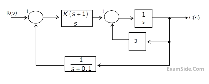
 (a) Draw the signal-flow graph that represents the system.
(b) Find the total number of loops in the graph and determine the loop-gains of all the loops.
(c) Find the number of all possible combination of non-touching loops taken two at a time.
(d) Determine the transfer function of the system using the signal-flow graph.
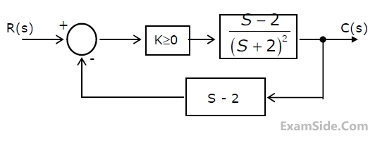
(a) Find the transfer function of the system and its characteristic equation.
(b) Use the Routh-Hurwitz criterion to determine the range of 'K' for which the system is stable.


(a) Find the desired location of the closed loop poles.
(b) Write down the requiredcharacteristic equation for the system. Hense determine the PD controller transfer function Gp(s) when K = 1.
(c) Sketch the root-locus for the system.


(a) Enter the logical values in the given Karnaugh map [figure2(b)] for the output
Y.
(b) Write down the expression for Y in sum-of products from using minimum
number of terms.
(c) Draw the circuit for the digital logic boxes using four 2-input NAND gates
only for each of the boxes.


(a) Calculate the cut-off wavelength and the guide wavelength for this mode.
(b) What are the other (TE or TM) modes that can propagate through the waveguide?
(c) If a = b = 2.29 cm, what are the modes which can propagate through the waveguide?

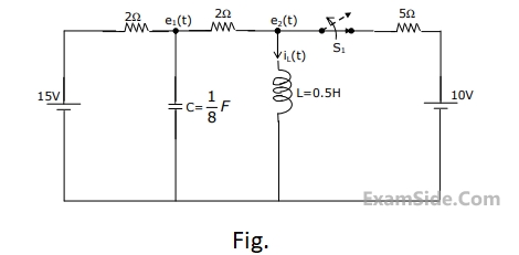
(a) Find $${i_L}\left( {{0^ + }} \right)$$.
(b) Find $${e_1}\left( {{0^ + }} \right)$$.
(c) Using nodal equations and Laplace transform approach, find an expression
for the voltage across the capacitor for all $$t\, = \,0$$.
(a) $${E_1} = \,10\,\angle \,{0^{ \circ \,}}\,V$$
(b) $${I_1} = \,10\,\angle \,{0^{ \circ \,}}\,A$$
(c) A source $$10\,\angle \,{0^{ \circ \,}}\,V$$ in series with a 0.25 $$\Omega $$ resistor is connected to the input port.

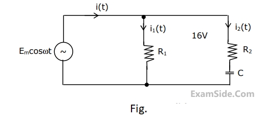
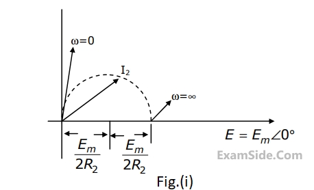
In figure, the value of the load resistor R which maximizes the power delivered to it is

The voltage e0 in Fig. is

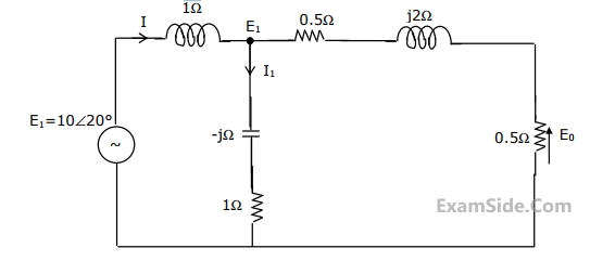

The voltage e0 in figure is

$${h_1}$$(t), = 1;
$${h_2}$$(t), = U(t);
$${h_3}(t)\, = \,{{U(t)} \over {t + 1}}$$;
$${h_4}(t)\, = {e^{ - 3t}}U(t)$$ ,
where U (t) is the unit step function. Which of these system is time invariant, causal, and stable?
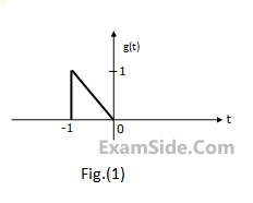
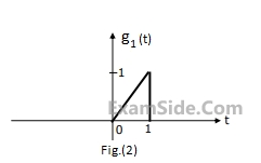
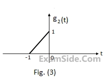
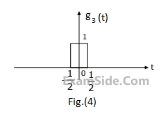
$$G(\omega ) = {1 \over {{\omega ^2}}}({e^{j\omega }} - j\omega {e^{j\omega }} - 1)$$.
Using this information, and the time-shifting and time-scaling properties, determine and Fourier transform of signals in Fig (2), (3) and (4).