GATE ECE

The N/W components have following values, RC = 2$$k\Omega $$,
RS = $$1.4k\Omega $$,
RE = $$100\Omega $$.
The transistor has specifications, $$\beta \,\, = \,\,100$$
and base spreading resistance $${r_{bb\,}}^1\, = \,100\Omega $$
Evaluate input resistance Ri for two cases. At a frequency of 10 kHz
(a)CE, the bypass capacitor across RE is 25 $$\mu F$$
(b)The bypass capacitor CE is removed leaving RE unbypassed.


1. Voltage series configuration
2.Current shunt configuration
(a) increases input impedance
(b) decreases input impedance
(c) increases closed loop gain
(d) leads to ascillation.

The characteristics of the diode are given by the relation I = Is $$\left[ {{e^{{{qV} \over {KT}}}} - 1} \right],$$
Where V is the forward voltage across the diode
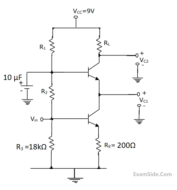
(a)Express V0 as a function of Vi assuming Vi> 0.
(b)If R = 100K$$\Omega $$ , Is = 1$$\mu $$A and $${{KT} \over q}\,\, = \,\,25mV$$
 Evaluate values of $${R_{A\,}}$$ and $${R_{B\,}}$$ and if the capacitor has the value of 0.01$$\mu $$F for the configuration closed. If necessary you can suggest modifications in the external circuit configuration.

The value of K should be
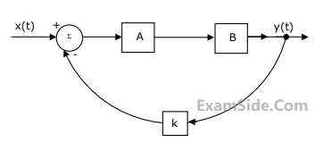
 (a) Find the transfer function $$\frac{y\left(s\right)}{x\left(s\right)}$$
when k =1.
(a) Find the transfer function $$\frac{y\left(s\right)}{x\left(s\right)}$$
when k =1.
(b) Find the impulse response when k = 0.
(c) Find the values of k for which the system becomes unstable.

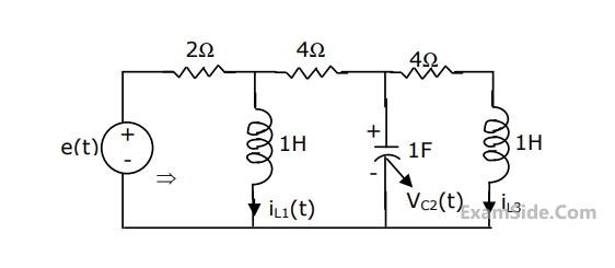
For the circuit shown in the figure, choose state variables as $${x_{1,}}{x_{2,}}{x_3}$$ to be $${i_{L1}}\left( t \right),{v_{c2}}\left( t \right),{i_{L3}}\left( t \right)$$
Wriote the state equations
$$$\left[ {\matrix{ {\mathop {{x_1}}\limits^ \bullet } \cr {\mathop {{x_2}}\limits^ \bullet } \cr {\mathop {{x_3}}\limits^ \bullet } \cr } } \right] = A\left[ {\matrix{ {{x_1}} \cr {{x_2}} \cr {{x_3}} \cr } } \right] + B\left[ {e\left( t \right)} \right]$$$The Clock has a period of 50ns and transitions take place at the rising clock edge.
(a) Give the sequence generated at Q0 till it repeats.
(b) What is the repetition rate for the generated sequence?


$${I_{OH}}{\,_{\max \,}} = \, - $$ 0.4mA, $${I_{OL}}$$ max = 8mA, $${I_{IH}}$$ max = $$\mu $$A , $${I_{IL\,}}_{\max \,}$$=0.1mA. The fan out based on the above will be


From which address will be text instruction be fetched?


(a) Find the impedance to the right of $$\left( {A,\,\,\,\,\,\,B} \right)$$ at $$\omega \,\,\, = \,\,\,\,0$$ rad/sec and $$\omega \,\,\, = \,\,\,\,\infty $$ rad/sec.
(b) If $$\omega \,\,\, = \,\,\,\,{\omega _0}$$ rad/sec and $${i_1}\left( t \right) = \,\,{\rm I}\,\,\,\sin \,\left( {{\omega _0}t} \right)\,{\rm A},$$ where $${\rm I}$$ is positive, $${{\omega _0}\,\, \ne \,\,0}$$, $${{\omega _0}\,\, \ne \,\,\infty }$$, then find $${\rm I}$$, $${{\omega _0}}$$ and $${i_2}\left( t \right)$$

The voltage V in Fig. is equal to

The current "i4" in the circuit of Fig. is equal to

The voltage V in Fig. is always equal to

 For the circuit shown in Fig. choose state variables $$X_1,\;X_2,\;X_3$$ to be $$i_{L1}\left(t\right),\;v_{C2}\left(t\right),\;i_{L3}\left(t\right)$$
(a) Write the state equations
$$$\begin{bmatrix}{\dot X}_1\\{\dot X}_2\\{\dot X}_3\end{bmatrix}\;=\;A\;\begin{bmatrix}X_1\\X_2\\X_3\end{bmatrix}\;+\;B\left[e\left(t\right)\right]$$$(b) If e(t) = 0, t $$\geq$$ 0, $$i_{L1}\left(0\right)\;=\;0,\;v_{C2}\left(0\right)\;=\;0,\;i_{L3}\left(0\right)\;=\;1A,$$ then what would the total energy dissipated in the registors in the interval $$\left(0,\infty\right)$$ be
In the circuit of Fig. when R = 0 Ω, the current iR equals 10 A.
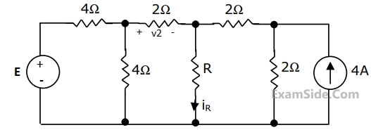
(a) Find the value of R for which it absorbs maximum power.
(b) Find the value of E.
(c) Find v2 when R = $$\infty$$ ( open circuit)


The voltage V in Fig. is

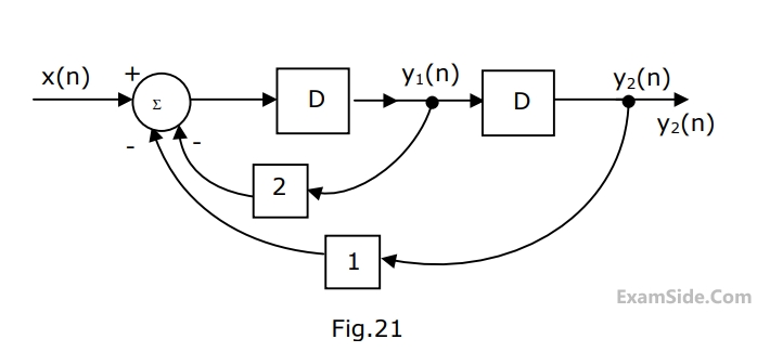
(a) Find the expression for $${y_1}\left( n \right)$$ and $${y_2}\left( n \right)$$ in terms of $$x\left( n \right).$$
(b) Find the transfer function $${y_2}\left( z \right)/X\left( z \right)$$ in the $$z$$-domain.
(c) If $$x\left( n \right) = 1$$ at $$n = 0$$ or $$x\left( n \right) = 0$$ otherwise
Find $${y_2}\left( n \right).$$
In the case of a linear time invariant system
List - 1
(1) Poles in the right half plane implies.
(2) Impulse response zero for $$t \le 0$$ implies.
List - 2
(A) Exponential decay of output
(B) System is causal
(C) No stored energy in the system
(D) System is unstable
Item-1
(1) The Fourier transform of g (t - 2) is
(2) The Fourier transform of g (t/2) is
Item - 2
(A) G(f) $$e^{-j\left(4\mathrm{πf}\right)}$$
(B) G(2f)
(C) 2G(2f)
(D) G(f-2)
Match each of the items 1, 2 on the left with the most appropriate item A, B, C or D on the right.
(a) Find the transfer function $${{Y(s)} \over {X(s)}}$$, when k=1
(b) Find the impulse response, when k = 0
(c) Find the value of k for which the system becomes unstable.
$$$\left[ {\matrix{ {Note:u(t)\, \equiv \,0} & {t\, \le \,0} \cr {\,\,\,\,\,\,\,\,\,\,\,\,\,\,\,\,\,\,\,\,\,\,\, \equiv 1} & {t\, > \,0} \cr } } \right]$$$