GATE ECE
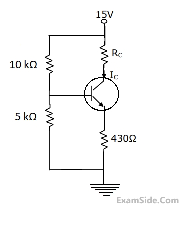
$${I_C}\, = \,1.3\,mA,\,{R_C}\, = \,2\,k\Omega ,\,{R_E}\, = \,500\,\Omega ,$$
$${V_T}\, = \,26\,mV,\,\beta \, = \,100,\,{V_{CC}}\, = \,15V,$$
$${V_s}\, = \,0.01\,\sin \left( {\omega t} \right)\,V\,and\,{C_b}\, = \,{C_C}\, = \,10\,\mu F.$$
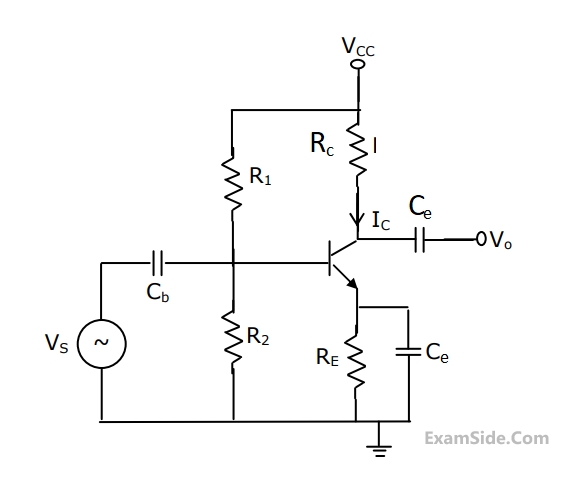
(a)What is the small-signal voltage gain, $${A_V} = {V_0}/{V_s}?$$
(b)What is the approximate $${A_{v,}}\,\,if\,\,{C_e}\,\,$$ is removed?
(c)What will $${V_0}\,be\,if\,{C_b}$$ is short circuited?
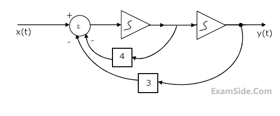
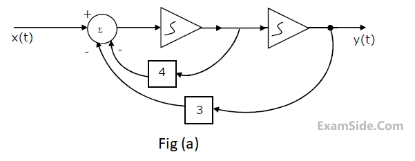
(a) Find the transfer function.
(b) For the step response of the system [i.e. find y(t) when x(t) is a unit step function and the initial conditions are zero]
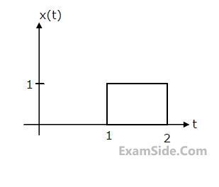
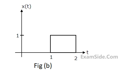
(c) Find y(t), if x(t) is as shown in Fig. and the initial conditions are zero.
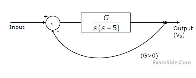
(a) Find the closed loop transfer function.
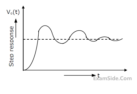
(b) Find the minimum value of G for which the step response of the system would exhibit an overshoot, as shown in Figure.
(c) For G equal to twice this minimum value, find the time period T indicated in Figure.
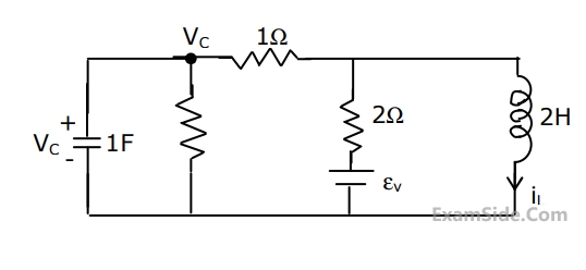
(a) Find the eigen values (natural frequencies) of the system.
(b)If u(t)=$$\delta \left( t \right)$$ and x1(0+)=x2(0+)=0, find x1(t),x2(t) and y(t), for t>0.
(c)When the input is zero, choose initial conditions $${x_1}\left( {{0^ + }} \right)$$ and $${x_2}\left( {{0^ + }} \right)$$ such that $$y\left( t \right) = A{e^{ - 2t}}$$ for t>0
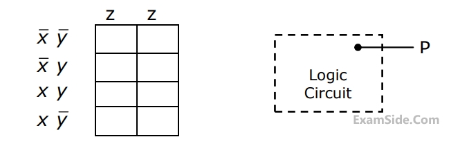
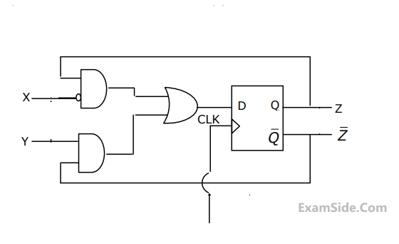
(a) Enter the logical values in the K-map in the format shown in figure 3(a). Derive
the minimal Boolean sum-of-products expression whose output is zero when a majority of the pumps fail.
(b) The above expression is implemented using logic gates, and point P is the
output of this circuit, as shown in figure 3(b). P is at 0 V when a majority of the pumps fails and is at 5 V otherwise. Design a circuit to drive the LED using this output. The current through the LED should be 10 mA and the voltage drop across it is 1V. Assume that P can source or sink 10 mA and a 5 V supply is available.
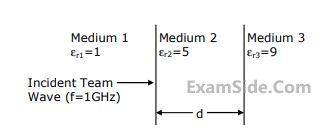
(a) Wave impedance in mediums 2 and 3.
(b) d such that medium 2 acts as a quarter wave $$(\lambda /40$$)transformer.
(c) Reflection coefficient $$(\Gamma )$$ and voltage standing wave ratio (VSWR) at the interface of the medium 1 and 2, when $$d = \lambda /4$$.
$$h\left( t \right) = \int\limits_0^t {f\left( T \right)} g\left( {t - T} \right)dT$$
then $$L\left\{ {h\left( t \right)} \right\}$$ is _______________.
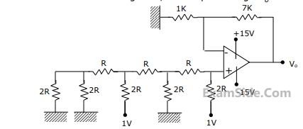
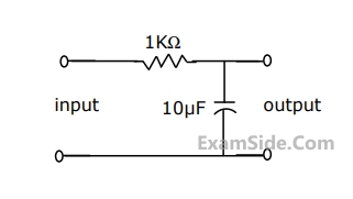
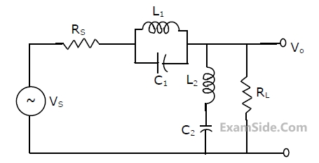
(a) Find the voltage transfer function of the network.
(b) Find L, and draw the configuration of the network.
(c) Find the impulse response of the network.
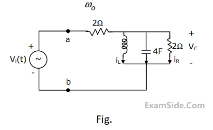
(a)Find the frequency $${\omega _0}$$ at which the magnitude of the impedance across terminals a, b reaches maximum.
(b) Find the impedance across a, b at the frequency $${\omega _0}$$.
(c) If $${v_i}\left( t \right) = V\,\,\sin \left( {{\omega _0}t} \right),$$ find $${i_L}\left( t \right),\,\,{i_c}\left( t \right),{i_R}\left( t \right).$$
In the circuit of Fig., the votage v(t) is

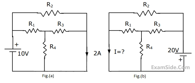
Use the data of Fig.(a). The current i in the circuit of Fig.(b) is
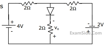
For the circuit in Fig. the voltage V0 is
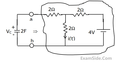
(a) Find the Thevenin equivalent of the sub circuit faced by the capacitor across the terminals a, b.
(b) Find $$v_c\left(t\right),\;t>0,\;given\;v_c(0)\;=\;0.$$
(c) Find i(t), t>0.
In the circuit of Fig., the value of the voltage source E is

(a) Find the transfer function.
(b) For the step response of the system [i.e. find y(t) when x(t) is a unit step function and the initial conditions are zero]
(c) Find y(t), if x(t) is as shown in Fig.(b), and the initial conditions are zero.
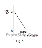
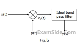
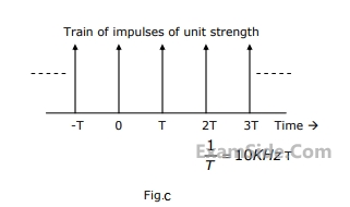
(a) Calculate the Fourier series coefficients $${c_n}$$ in the Fourier expansion of p(t) in form $$p(t) = \sum\limits_{n = - \infty }^{ + \infty } {{c_n}} \,\exp \,\,(j\,n\,2\pi \,t/T)$$.
(b) Find the Fourier Transform of p(t).
(c) Obtain and sketch the spectrum of $${x_s}(t)$$.
(d) Obtain and sketch the spectrum of y(t).