1
JEE Advanced 2018 Paper 1 Offline
MCQ (More than One Correct Answer)
+4
-1

In the figure below, the switches $${S_1}$$ and $${S_2}$$ are closed simultaneously at $$t=0$$ and a current starts to flow in the circuit. Both the batteries have the same magnitude of the electromotive force (emf) and the polarities are as indicated in the figure. Ignore mutual inductance between the inductors. The current $$I$$ in the middle wire reaches its maximum magnitude $${I_{\max }}$$ at time $$t = \tau $$ . Which of the following statements is (are) true?

2
JEE Advanced 2017 Paper 2 Offline
MCQ (More than One Correct Answer)
+4
-2
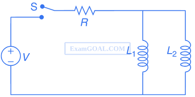
A source of constant voltage V is connected to a resistance R and two ideal inductors L1 and L2 through a switch S as shown. There is no mutual inductance between the two inductors. The switch S is initially open. At t = 0, the switch is closed and current begins to flow. Which of the following options is/are correct?
3
JEE Advanced 2017 Paper 1 Offline
MCQ (More than One Correct Answer)
+4
-1
A circular insulated copper wire loop is twisted to form two loops of area $$A$$ and $$2A$$ as shown in the figure. At the point of crossing the wires remain electrically insulated from each other. The entire loop lies in the plane (of the paper). A uniform magnetic field $$\overrightarrow B $$ points into the plane of the paper. At $$t=0,$$ the loop starts rotating about the common diameter as axis with a constant angular velocity $$\omega $$ in the magnetic field.
Which of the following options is/are correct?

Which of the following options is/are correct?
4
JEE Advanced 2016 Paper 2 Offline
MCQ (More than One Correct Answer)
+4
-2
A rigid wire loop of square shape having side of length L and resistance R is moving along the X-axis with a constant velocity v0 in the plane of the paper. At t = 0, the right edge of the loop enters a region of length 3L where there is a uniform magnetic field B0 into the plane of the paper, as shown in the figure. For sufficiently large v0, the loop eventually crosses the region. Let x be the location of the right edge of the loop. Let v(x), I(x) and F(x) represent the velocity of the loop, current in the loop, and force on the loop, respectively, as a function of x. Counter-clockwise current is taken as positive.
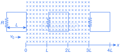
Which of the following schematic plot(s) is (are) correct? (Ignore gravity)
Which of the following schematic plot(s) is (are) correct? (Ignore gravity)
A

B

C

D

JEE Advanced Subjects
Browse all chapters by subject
Physics
Mechanics
Units & Measurements Motion Laws of Motion Work Power & Energy Impulse & Momentum Rotational Motion Properties of Matter Heat and Thermodynamics Simple Harmonic Motion Waves Gravitation Motion in a Plane
Electricity
Electrostatics Current Electricity Capacitor Magnetism Electromagnetic Induction Alternating Current Electromagnetic Waves
Optics
Modern Physics
Chemistry
Physical Chemistry
Some Basic Concepts of Chemistry Structure of Atom Redox Reactions Gaseous State Chemical Equilibrium Ionic Equilibrium Solutions Thermodynamics Chemical Kinetics and Nuclear Chemistry Electrochemistry Solid State Surface Chemistry
Inorganic Chemistry
Periodic Table & Periodicity Chemical Bonding & Molecular Structure Isolation of Elements Hydrogen s-Block Elements p-Block Elements d and f Block Elements Coordination Compounds Salt Analysis
Organic Chemistry
Mathematics
Algebra
Quadratic Equation and Inequalities Sequences and Series Mathematical Induction and Binomial Theorem Matrices and Determinants Permutations and Combinations Probability Vector Algebra 3D Geometry Statistics Complex Numbers
Trigonometry
Coordinate Geometry
Calculus