Current Electricity · Physics · JEE Advanced
MCQ (Single Correct Answer)
A metal wire of cross-sectional area 0.5 mm2 and length 100 m is connected across a battery of e.m.f. 2 V and internal resistance 1 Ω. The density, atomic mass and electrical conductivity of the metal are 6.35 × 10³ kg m−3, 63.5 gm/mole and 2 × 10⁸ mho m−1, respectively. Assuming one conduction electron per atom of the metal, the drift velocity (in mm s−1) of the electrons in the wire is:
[Take Avogadro’s number as 6 × 10²³ and charge of the electron as 1.6 × 10⁻¹⁹ C.]
During an experiment with a metre bridge, the galvanometer shall a null point when the jockey is pressed at 40.0 cm using a standard resistance of 90$$\Omega$$, as shown in the figure. The least count of the scale used in the meter bridge is 1 mm. The unknown resistance is

If the direct transmission method with a cable of resistance 0.4 $$\Omega$$ km$$-$$1 is used, the power dissipation (in %) during transmission is
A meter bridge is set up as shown, to determine an unknown resistance X using a standard 10 $$\Omega$$ resistor. The galvanometer shows null point when tapping-key is at 52 cm mark. The end-corrections are 1 cm and 2 cm, respectively, for the ends A and B. The determined value of X is

Incandescent bulbs are designed by keeping in mind that the resistance of their filament increases with the increase in temperature. If at room temperature, 100, 60 and 40 W bulbs have filament resistances R100, R60 and R40 respectively, the relation between these resistances is
To verify Ohm's law, a student is provided with a test resitor RT, a high resistance R1, a small resistance R2, two identical galvanometers G1 and G2, and a variable voltage source V. The correct circuit to carry out the experiment is
Consider a thin square sheet of side L and thickness, made of a material of resistivity $$\rho$$. The resistance between two opposite faces, shown by the shaded areas in the figure is

Figure shows three resistor configurations R1, R2 and R3 connected to 3 V battery. If the power dissipated by the configuration R1, R2 and R3 is P1, P2 and P3, respectively, then


STATEMENT - 1
In a Meter Bridge experiment, null point for an unknown resistance is measured. Now, the unknown resistance is put inside an enclosure maintained at a higher temperature. The null point can be obtained at the same point as before by decreasing the value of the standard resistance.
and
STATEMENT - 2
Resistance of a metal increases with increase in temperature.
A resistance of 2 $$\Omega$$ is connected across one gap of a metre-bridge (the length of the wire is 100 cm) and an unknown resistance, greater than 2 $$\Omega$$, is connected across the other gap. When these resistance are interchanged, the balance point shifts by 20 cm. Neglecting any corrections, the unknown resistance is
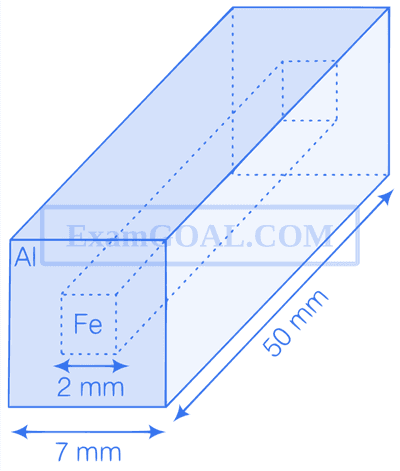
Consider a cylindrical element as shown in the figure. The current that flows through the element is I and resistivity of material of the cylinder is $\rho$. Choose the correct option out the following

An unknown resistance X is to be determined using resistances R$$_1$$, R$$_2$$ or R$$_3$$. Their corresponding null points are A, B and C. Find which of the above will give the most accurate reading and why ?

Numerical
As shown in the figure, the resistance of a galvanometer G can be found by the half-deflection method. Here the resistance R2 is adjusted such that when the key K is closed the deflection in the galvanometer becomes half of the value as compared to when K is open. Half-deflection is obtained at R2 = 4 $\Omega$ and thus the galvanometer resistance is found to be 6 $\Omega$. In this half-deflection condition the current (in mA) through the resistor R1 is :

Two resistances $R_{1}=X \Omega$ and $R_{2}=1 \Omega$ are connected to a wire $A B$ of uniform resistivity, as shown in the figure. The radius of the wire varies linearly along its axis from $0.2 \mathrm{~mm}$ at $A$ to $1 \mathrm{~mm}$ at $B$. A galvanometer $(\mathrm{G})$ connected to the center of the wire, $50 \mathrm{~cm}$ from each end along its axis, shows zero deflection when $A$ and $B$ are connected to a battery. The value of $X$ is ____________.

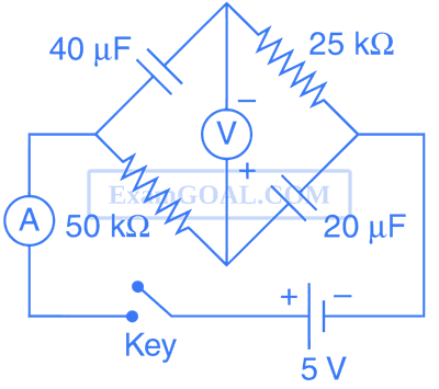
In the following circuit $C_{1}=12 \mu F, C_{2}=C_{3}=4 \mu F$ and $C_{4}=C_{5}=2 \mu F$. The charge stored in $C_{3}$ is ____________ $\mu C$.

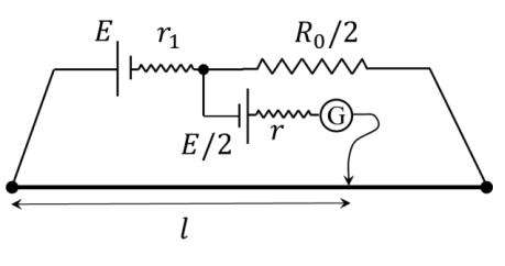


Two batteries of different emfs and different internal resistance are connected as shown. The voltage across AB in volts is __________.

When two identical batteries of internal resistance 1 $$\Omega$$ each are connected in series across a resistor R, the rate of heat produced in R is J1. When the same batteries are connected in parallel across R, the rate is J2. If J1 = 2.25 J2, then the value of R in $$\Omega$$ is __________.
MCQ (More than One Correct Answer)
$P_{1}$ and $P_{2}$ are the power dissipations in Circuit-1 and Circuit-2 when the switches $\mathrm{S}_{1}$ and $\mathrm{S}_{2}$ are in open conditions, respectively.
$Q_{1}$ and $Q_{2}$ are the power dissipations in Circuit-1 and Circuit-2 when the switches $\mathrm{S}_{1}$ and $\mathrm{S}_{2}$ are in closed conditions, respectively.
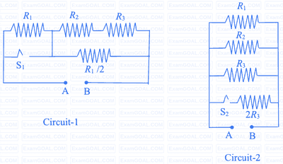
Which of the following statement(s) is(are) correct?
The figure shows a circuit having eight resistances of $1 \Omega$ each, labelled $R_{1}$ to $R_{8}$, and two ideal batteries with voltages $\varepsilon_{1}=12 \mathrm{~V}$ and $\varepsilon_{2}=6 \mathrm{~V}$.

Which of the following statement(s) is(are) correct?


Which of the statement(s) is/are correct?

For the resistance network shown in the figure, choose the correct option(s).

For the circuit shown in the figure

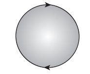
In the given diagram, a line of force of a particular force field is shown. Out of the following options, it can never represent