1
GATE ECE 2004
MCQ (Single Correct Answer)
+2
-0.67
For the lattice circuit shown in Fig., $${Z_a} = j\,2\,\Omega \,\,and\,\,{Z_b} = \,\,2\Omega $$. The values of the open circuit impedance parameters
$$Z\,\left[ {\matrix{ {{Z_{11}}} & {{Z_{12}}} \cr {{Z_{21}}} & {{Z_{22}}} \cr } } \right]\,$$ are
$$Z\,\left[ {\matrix{ {{Z_{11}}} & {{Z_{12}}} \cr {{Z_{21}}} & {{Z_{22}}} \cr } } \right]\,$$ are
2
GATE ECE 2004
MCQ (Single Correct Answer)
+2
-0.6
For the circuit shown in Figure, the initial conditions are zeros. Its transfer function
$$H(s) = {{{V_c}\,(s)} \over {{V_i}\,(s)}}$$ is

3
GATE ECE 2003
MCQ (Single Correct Answer)
+2
-0.6
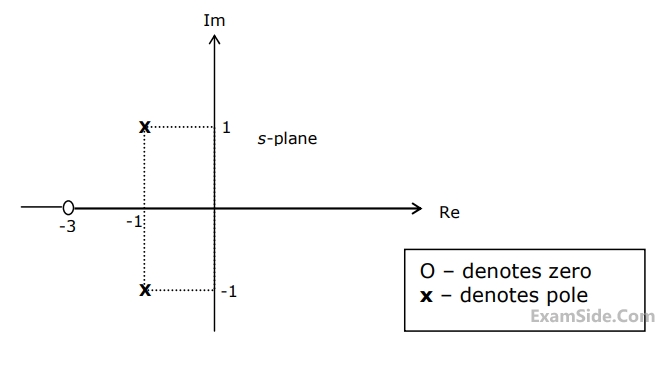
The driving-point impedance Z(s) of a network has the pole-zero locations as shown in figure. If Z(0) = 3, then Z(s) is
4
GATE ECE 2003
MCQ (Single Correct Answer)
+2
-0.6
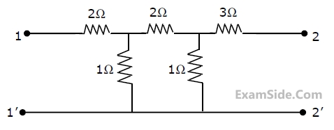
The impedance parameters Z11 and Z12 of the two-port network in figure are
GATE ECE Subjects
Browse all chapters by subject
General Aptitude
Network Theory
Microprocessors
Signals and Systems
Discrete Fourier Transform and Fast Fourier Transform Discrete Time Signal Fourier Series Fourier Transform Continuous Time Signal Laplace Transform Fourier Transform Representation of Continuous Time Signal Fourier Series Transmission of Signal Through Continuous Time LTI Systems Miscellaneous Sampling Continuous Time Linear Invariant System Discrete Time Linear Time Invariant Systems Discrete Time Signal Z Transform Transmission of Signal Through Discrete Time Lti Systems
Electromagnetics
Digital Circuits
Electronic Devices and VLSI
Control Systems
Communications
Engineering Mathematics