1
GATE EE 2005
MCQ (Single Correct Answer)
+2
-0.6
Select the circuit which will produce the given output $$Q$$ for the input signals $${X_1}$$ and $${X_2}$$ given in the figure.

A

B

C

D

2
GATE EE 2003
MCQ (Single Correct Answer)
+2
-0.6
The shift register shown in Fig. is initially loaded with the bit pattern $$1010.$$ Subsequently the shift register is clocked, and with each clock pulse the pattern gets shifted by one bit position to the right. With each shift, the bit at the serial input is pushed to the left most position $$(MSB).$$ After how many clock pulses will the content of the shift register become $$1010$$ again?

3
GATE EE 2000
MCQ (Single Correct Answer)
+2
-0.6
A dual-slope analog-to-digital converter uses an $$N$$-bit counter. When the input signal $${V_a}$$ is being integrated, the counter is allowed to count up to a value:
4
GATE EE 2000
Subjective
+2
-0
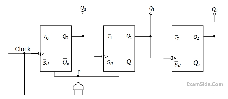
The counter shown in Fig. is initially in state $${Q_2} = 0,\,{Q_1} = 1,\,{Q_0} = 0.$$ With reference to the $$CLK$$ input, draw waveforms for $${Q_2},{Q_1},{Q_0}$$ and $$P$$ for the next three $$CLK$$ cycles.
GATE EE Subjects
Browse all chapters by subject
Electric Circuits
Electrical Machines
Engineering Mathematics
Signals and Systems
Power Electronics
Power System Analysis
Digital Electronics
Analog Electronics
Electromagnetic Fields
Control Systems
Electrical and Electronics Measurement
General Aptitude