Sequential Circuits · Digital Electronics · GATE EE
Marks 1
In the circuit, the present value of $Z$ is $1$. Neglecting the delay in the combinatorial circuit, the values of $S$ and $Z$, respectively, after the application of the clock will be

A MOD-2 and a MOD-5 up-counter when cascaded together results in a MOD _________ counter. (in integer).
The maximum clock frequency in MHz of a 4-stage ripple counter, utilizing flip-flops, with each flip-flop having a propagation delay of 20 ns, is ________. (round off to one decimal place).
A 16 -bit synchronous binary up-counter is clocked with a frequency $f_{c l k}$. The two most significant bits are ORed together to form an output $Y$. Measurements shows that $Y$ is periodic and the duration for which $Y$ the remains high in each period is 24 ms . The clock frequency $f_{\text {clk }}$ is $\_\_\_\_$ MHz. (Round off to 2 decimal places)

The logic gate represented by the state diagram is


Marks 2
A counter is constructed with three D flip-flops. The input-output pairs are named as $\left(D_0, Q_0\right)$, $\left(D_1, Q_1\right)$ and $\left(D_2, Q_2\right)$, where the subscript 0 denotes LSB. The output sequence is desired to be Graycode sequence $000,001,011,010,110,111,101$ and 100 , repeating periodically. Note that the bits are listed in the $Q_2 Q_1 Q_0$ format. The combination logic expression for $D_1$ is

The minimum number if clock cycles after which the output $$Z$$ would again become zero is _____________.


It the state $${Q_A}{Q_B}$$ of the counter at the clock time $${t_n}$$ is $$'10'$$ then the state $${Q_A}{Q_B}$$ of the counter at $${t_n} + 3$$ (after three clock cycles) will be


Marks 5


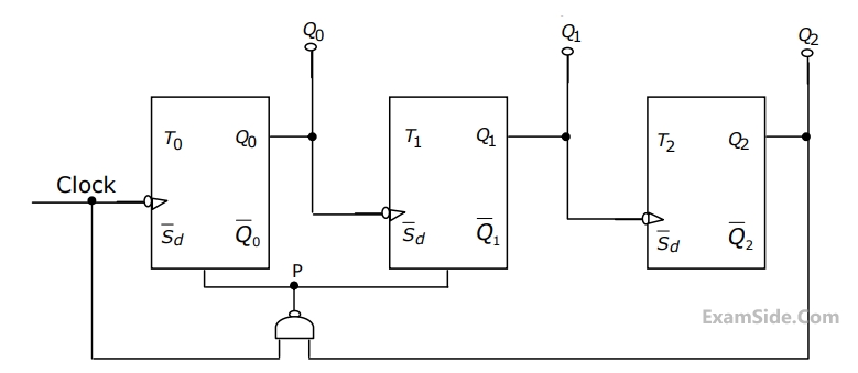
$$(a)$$ Create a table of $${Q_0},{Q_1},{Q_2}$$ and $$A$$ in the format given below for $$10$$ successive
$$\,\,\,\,\,\,\,\,$$ input cycles of the clock $$CLK1.$$
$$(b)$$ Determine the module number of the counter.
$$(c)$$ Modify the circuit of Fig. to create a modulo$$-6$$ counter using the same
$$\,\,\,\,\,\,\,$$ components used in the figure.


$$(b)$$ Sketch the output waveforms at $${Q_1},{Q_2}$$ and $${Q_3}$$.
$$(c)$$ What function does this circuit perform.