Diode Circuits and Applications · Analog Electronics · GATE EE
Marks 1
In the linear regulator circuit shown, the base to emitter voltage $V_{B E}$ of the BJT is 0.6 V . The Zener diode clamps the base voltage to 5.4 V . Ignore the biasing current of the Zener diode and BJT. The maximum possible efficiency of the regulator circuit is
$\_\_\_\_$ % (Round off to one decimal place)

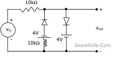
For the circuit shown below with ideal diodes, the output will be

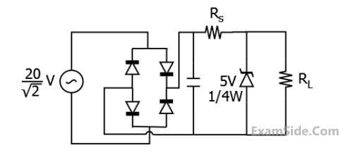
In the circuit shown, a 5 V Zener diode is used to regulate the voltage across load $R_0$. The input is an unregulated DC voltage with a minimum value of 6 V and a maximum value of 8 V . The value of $R_s$ is $6 \Omega$. The Zener diode has a maximum rated power dissipation of 2.5 W . Assuming the Zener diode to be ideal, the minimum value of $R_0$ is $\_\_\_\_$ $\Omega$.

In the circuit shown, the input $V_i$ is a sinusoidal AC voltage having an rms value of $230 \mathrm{~V} \pm 20 \%$. The worst case peak-inverse voltage seen across any diode is $\_\_\_\_$ V. (Round off to 2 decimal places)


The $$DC$$ components of voltages $${v_1}$$ and $${v_2},$$ respectively are


The current in the circuit is


The element connected between $$' a '$$ and $$' b '$$ could be
(a)

(b)
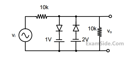
If such diodes are used in the clipper circuit of figure given above, the output voltage (V0) of the circuit will be


Marks 2
In the given circuit, the diodes are ideal. The current I through the diode D1 in milliamperes is _____ (rounded off to two decimal places).

All the elements in the circuit shown in the following figure are ideal. Which of the following statements is/are true?

The Zener diode in circuit has a breakdown voltage of 5 V. The current gain $$\beta$$ of the transistor in the active region in 99. Ignore base-emitter voltage drop $$V_{BE}$$. The current through the 20 $$\Omega$$ resistance in milliamperes is ___________ (Round off to 2 decimal places).

The waveform shown in solid line is obtained by clipping a full-wave rectified sinusoid (shown dashed). The ratio of the rms value of the full-wave rectified waveform to the rms value of the clipped waveform is $\_\_\_\_$ . (Round off to 2 decimal places,)


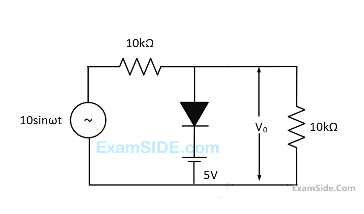
Assuming forward voltage drops of the diodes to be $$0.7V,$$ the input-output transfer characteristics of the circuit is