Transient Response · Electric Circuits · GATE EE
Marks 1
The circuit shown in the figure with the switch S open, is in steady state. After the switch S is closed, the time constant of the circuit in seconds is

In the circuit shown below, the switch S is closed at t = 0. The magnitude of the steady state voltage, in volts, across the 6 $$\Omega$$ resistor is ________. (round off to two decimal places).

In the circuit, switch 'S' is in the closed position for a very long time. If the switch is opened at time t = 0, then iL (t) in amperes, for t ≥ 0 is


Marks 2
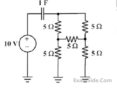
The electrical network shown has an independent voltage source $(10 \mathrm{~V})$ and a current source ( $1 \mathrm{u}(\mathrm{t}) \mathrm{mA}$ ).

The voltage across the capacitor at time instants (in seconds) $t=0^{+}, t=0.50$, and $t=\infty$, respectively, is:

The circuit shown in the figure is initially in the steady state with the switch K in open condition and $$\overline K $$ in closed condition. The switch K is closed and $$\overline K $$ is opened simultaneously at the instant $$t=t_1$$, where $$t_1 > 0$$. The minimum value of $$t_1$$ in milliseconds, such that there is no transient in the voltage across the 100 $$\mu$$F capacitor, is ___________ (Round off to 2 decimal places).

A 100 Hz square wave, switching between 0 V and 5 V, is applied to a CR high-pass filter circuit as shown. The output voltage waveform across the resistor is 6.2 V peak-to-peak. If the resistance R is 820 Ω, then the value C is ______ μF.
(Round off to 2 decimal places)


If, at $$t = {0^ + }$$, the voltage across the coil is $$120$$ $$V,$$ the value of resistance $$R$$ is

For the value of $$R$$ obtained in the above question, the time taken for $$95\% $$ of the stored energy to be dissipated is close to


Marks 5


$$L = 2\,H,\,\,{R_1} = 10\,\Omega ,\,\,{R_2} = 2\,\Omega ,\,\,C = 0.25\,\mu F$$
$$(a)$$ Determine $${i_L}\left( 0 \right)$$ and $${V_C}\left( 0 \right)$$
$$(b)$$ Write the differential equation governing $${V_C}\left( t \right)$$ for $$t>0$$
$$(c)$$ Compute the steady state value of $${V_C}\left( t \right)$$
