Marks 1
1
A bulb in staircase has two switches, one switch being at the ground floor and the other one at the first floor. The bulb can be turned $$ON$$ and also can be turned $$OFF$$ by any one of the switches irrespective of the state of the other switch. The logic of switching of the bulb resembles
GATE EE 2013
2
The complete set of only those Logic Gates designated as Universal gates is
GATE EE 2009
3
The digital circuit using two inverters shown in figure will act as

GATE EE 2004
4
The output of a logic gate is $$''1''$$ when all its inputs are at logic $$''0''.$$ The gate is either
GATE EE 2001
5
The Boolean expression for the output of the logic circuit shown in figure is

GATE EE 1996
Marks 2
1
Neglecting the delays due to the logic gates in the circuit shown in figure, the decimal equivalent of the binary sequence [ABCD] of initial logic states, which will not change with clock, is ___________.

GATE EE 2023
2
$$A,B,C$$ and $$D$$ are input bits, and $$Y$$ is the output bit in the $$XOR$$ gate circuit of the figure below. Which of the following statements about the sum $$S$$ of $$A,B,C,D$$ and $$Y$$ is correct?

GATE EE 2007
3
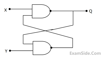
In the figure, as long as $${X_1} = 1$$ and $${X_2} = 1,$$ the output $$Q$$ remains

GATE EE 2005
4
A digital circuit which compares two numbers $${A_3}{A_2}{A_1}{A_0},\,\,{B_3}{B_2}{B_1}{B_0}$$ is shown in Fig. To get output $$Y=0,$$ choose one pair of correct input numbers

GATE EE 2004
5
For the circuit shown in Fig. the Boolean expression for the output $$Y$$ in terms of inputs $$P,$$ $$Q,$$ $$R$$ and $$S$$ is

GATE EE 2002
6
For a flip-flop formed from two $$NAND$$ gates as shown in figure. The unusable state corresponds to
GATE EE 1999
7
The logic function $$f = \overline {\left( {x.\overline y } \right) + \left( {\overline x .y} \right)} $$ is the same as
GATE EE 1999