Sinusoidal Steady State Analysis · Electric Circuits · GATE EE

Start Practice

Marks 1

1

The value of parameters of the circuit shown in the figure are

$${R_1} = 2\Omega ,{R_2} = 2\Omega ,{R_3} = 3\Omega ,L = 10$$ mH, $$C = 100$$ $$\mu$$F

For time t < 0, the circuit is at steady state with the switch 'K' in closed condition. If the switch is opened at t = 0, the value of the voltage across the inductor (V$$_L$$) at t = 0$$^+$$ in Volts is ___________ (Round off to 1 decimal place).

GATE EE 2023 Electric Circuits - Sinusoidal Steady State Analysis Question 2 English

GATE EE 2023
2

An inductor having a Q-factor of 60 is connected in series with a capacitor having a Q-factor of 240. The overall Q-factor of the circuit is ________. (round off to nearest integer).

GATE EE 2022
3

The network shown below has a resonant frequency of 150 kHz and a bandwidth of 600 Hz. The Q-factor of the network is _______. (round off to nearest integer).

GATE EE 2022 Electric Circuits - Sinusoidal Steady State Analysis Question 4 English

GATE EE 2022
4
The mean square value of the given periodic waveform f(t) is_________. GATE EE 2017 Set 2 Electric Circuits - Sinusoidal Steady State Analysis Question 61 English
GATE EE 2017 Set 2
5
An inductor is connected in parallel with a capacitor as shown in the figure. GATE EE 2015 Set 1 Electric Circuits - Sinusoidal Steady State Analysis Question 59 English 
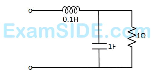
As the frequency of current i is increased, the impedance (Z) of the network varies as
GATE EE 2015 Set 1
6
Find the transformer ratios a and b that the impedance (Zin) is resistive and equal 2.5 Ω when the network is excited with a sine wave voltage of angular frequency of 5000 rad/s. GATE EE 2015 Set 2 Electric Circuits - Sinusoidal Steady State Analysis Question 60 English
GATE EE 2015 Set 2
7
The average power delivered to an impedance $$\left(4-j3\right)$$ Ω by a current $$5\cos\left(100\mathrm{πt}+100\right)\;A$$ is
GATE EE 2012
8
A two phase load draws the following phase currents: $$i_1\left(t\right)=I_m\sin\left(\omega t-\phi_1\right)$$, $$i_2\left(t\right)=I_m\cos\left(\omega t-\phi_2\right)$$. These currents are balanced if $$\phi_1$$ is equal to
GATE EE 2012
9
The r.m.s value of the current i(t) in the circuit shown below is GATE EE 2011 Electric Circuits - Sinusoidal Steady State Analysis Question 55 English
GATE EE 2011
10
The voltage applied to a circuit is $$100\sqrt2\cos\left(100\mathrm{πt}\right)$$ volts and the circuit draws a current of $$10\sqrt2\;\sin\left(100\mathrm{πt}+\mathrm\pi/4\right)$$ amperes. Taking the voltage as the reference phasor, the phasor representation of the current in amperes is
GATE EE 2011
11
The value of $$Z$$ in Fig., which is most appropriate to cause parallel resonance at $$500$$ $$Hz$$ is GATE EE 2004 Electric Circuits - Sinusoidal Steady State Analysis Question 27 English
GATE EE 2004
12
In a series $$RLC$$ circuit at resonance, the magnitude of the voltage developed across the capacitor
GATE EE 2001
13
A series $$R-L-C$$ circuit when excited by a $$10$$ $$V$$ sinusoidal voltage source of variable frequency, exhibits resonance at $$100$$ $$Hz$$ and has a $$3$$ $$dB$$ bandwidth of $$5$$ $$Hz.$$ The voltage across the inductor $$L$$ at resonace is

GATE EE 1999
14
The $$RMS$$ value of half $$-$$ wave rectified symmetrical square wave current of $$2A$$ is
GATE EE 1999
15
The current in the circuit shown in figure is GATE EE 1999 Electric Circuits - Sinusoidal Steady State Analysis Question 29 English
GATE EE 1999
16
A circuit with a resistor, inductor and capacitor in series is resonant at $${f_0}\,\,Hz.$$ If all the component values are now doubled, the new resonant frequency is
GATE EE 1998
17
A sinusoidal source of voltage $$V$$ and frequency $$f$$ is connected to a series circuit of variables resistance, $$R$$ and a fixed reactance, $$X.$$ The locus of the tip of the current phasor, $$I$$, as $$R$$ is varied from $$0$$ to $$\infty $$ is
GATE EE 1998
18
In the circuit shown in Fig. $$X$$ $$-$$ is an element which always absorbs power. During a particular operation, it sets up a current of $$1$$ $$amp$$ in the direction shown and absorbs a power $${P_{x}}.$$ It is possible that $$X$$ can absorb the same power $${P_x}$$ for another current $$i.$$ Then the value of this current is GATE EE 1996 Electric Circuits - Sinusoidal Steady State Analysis Question 34 English
GATE EE 1996
19
In the circuit of Figure, Ammeter $${A_2}$$ reads $$12$$ $$A$$ and $${A_3}$$ reads $$9$$ $$A.$$ $${A_1}$$ will read ______ GATE EE 1995 Electric Circuits - Sinusoidal Steady State Analysis Question 35 English
GATE EE 1995
20
A series $$R-L-C$$ circuit has the following parameter values:
$$R = 10\Omega ,\,\,L = 0.01\,H,\,\,C = 100\,\,m\,\,F.$$
The $$Q$$ factor of the circuit at resonance is
GATE EE 1995
21
At resonance, the given parallel circuit constituted by an iron - cored coil and a capacitor behaves like GATE EE 1994 Electric Circuits - Sinusoidal Steady State Analysis Question 37 English
GATE EE 1994
22
The following circuit (Fig.) resonates at GATE EE 1993 Electric Circuits - Sinusoidal Steady State Analysis Question 38 English
GATE EE 1993
23
In the following circuit (Fig.) $$i(t)$$ under steady state is GATE EE 1993 Electric Circuits - Sinusoidal Steady State Analysis Question 39 English
GATE EE 1993

Marks 2

1

For the circuit shown in the figure, the source frequency is 5000 rad/sec. The mutual inductance between the magnetically coupled inductors is 5 mH with their self inductances being 125 mH and 1 mH. The Thevenin’s impedance, $Z_{th}$, between the terminals P and Q in $\Omega$ is ______________ (rounded off to 2 decimal places).

GATE EE 2024 Electric Circuits - Sinusoidal Steady State Analysis Question 1 English
GATE EE 2024
2
A 0.1 μF capacitor charged to 100 V is discharged through a 1 kΩ resistor. The time in ms (round off to two decimal places) required for the voltage across the capacitor to drop to 1 V is ___________.
GATE EE 2019
3
In the circuit shown below, the value of capacitor C required for maximum power to be transferred to the load is GATE EE 2017 Set 2 Electric Circuits - Sinusoidal Steady State Analysis Question 54 English
GATE EE 2017 Set 2
4
In the circuit shown below, the supply voltage is 10sin(1000t) volts. The peak value of the steady state current through the 1Ω resistor, in amperes, is _________. GATE EE 2016 Set 1 Electric Circuits - Sinusoidal Steady State Analysis Question 52 English
GATE EE 2016 Set 1
5
The circuit below is excited by a sinusoidal source. The value of R, in Ω, for which the admittance of the circuit becomes a pure conductance at all frequencies is ________. GATE EE 2016 Set 1 Electric Circuits - Sinusoidal Steady State Analysis Question 53 English
GATE EE 2016 Set 1
6
The circuit shown in the figure has two sources connected in series. The instantaneous voltage of the AC source (in volt) is given by v(t) = 12sint. If the circuit is in steady-state, then the rms value of the current (in Ampere) flowing in the circuit is ______. GATE EE 2015 Set 1 Electric Circuits - Sinusoidal Steady State Analysis Question 48 English
GATE EE 2015 Set 1
7
A symmetrical square wave of 50% duty cycle has amplitude of ±15V and time period of 0.4$$\mathrm\pi$$ ms. This square wave is applied across a series RLC circuit with R = 5Ω, L = 10 mH, and C = 4μF. The amplitude of the 5000 rad/s component of the capacitor voltage (in Volt) is __________. GATE EE 2015 Set 2 Electric Circuits - Sinusoidal Steady State Analysis Question 49 English
GATE EE 2015 Set 2
8
Two identical coils each having inductance L are placed together on the same core. If an overall inductance of $$\alpha$$L is obtained by interconnecting these two coils, the minimum value of $$\alpha$$ is ________.
GATE EE 2015 Set 2
9
In the given network $$V_1=100\angle0^\circ V$$, $$V_2=100\angle-120^\circ V$$, $$V_3=100\angle+120^\circ V$$. The phasor current i (in Ampere) is GATE EE 2015 Set 2 Electric Circuits - Sinusoidal Steady State Analysis Question 51 English
GATE EE 2015 Set 2
10
The voltage across the capacitor, as sown in the figure, is expressed as $$$V_c\left(t\right)=A_1\sin\left(\omega_1t-\theta_1\right)+A_2\sin\left(\omega_2t-\theta_2\right)$$$ GATE EE 2014 Set 2 Electric Circuits - Sinusoidal Steady State Analysis Question 45 English The value of A1 and A2 respectively, are
GATE EE 2014 Set 2
11
The total power dissipated in the circuit, show in the figure, is 1kW. GATE EE 2014 Set 2 Electric Circuits - Sinusoidal Steady State Analysis Question 46 English 
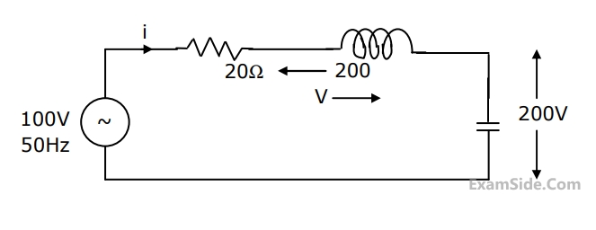
The ideal voltmeter, across the load, reads 200 V. The value of XL is _________.
GATE EE 2014 Set 2
12
A series RLC circuit is observed at two frequencies. At $$\omega_1$$ = 1k rad / s, we note that source voltage $$V_1=100\angle0^\circ V$$ results in a current $$I_1=0.03\angle31^\circ\;A$$. At $$\omega_2$$ = 2 k rad/s, the source voltage $$V_2=100\angle0^\circ\;V$$ results in a current $$I_2=2\angle0^\circ\;A$$. The closest values for R,L,C out of the following options are
GATE EE 2014 Set 3
13
Two magnetically uncoupled inductive coils have Q factors q1 and q2 at the chosen operating frequency. Their respective resistances are R1 and R2 . When connected in series, their effective Q factor at the same operating frequency is
GATE EE 2013
14
In the circuit shown, the three voltmeter readings are V1 = 220V, V2 = 122V , V3 = 136V. GATE EE 2012 Electric Circuits - Sinusoidal Steady State Analysis Question 43 English The power factor of the load is
GATE EE 2012
15
In the circuit shown, the three voltmeter readings are V1 = 220V, V2 = 122V , V3 = 136V. GATE EE 2012 Electric Circuits - Sinusoidal Steady State Analysis Question 42 English If RL=5 Ω , the approximate power consumption in the load is
GATE EE 2012
16
An RLC circuit with relevant data is given below. GATE EE 2011 Electric Circuits - Sinusoidal Steady State Analysis Question 40 English The current $${\underline I}_C$$ in the figure above is
GATE EE 2011
17
An RLC circuit with relevant data is given below. GATE EE 2011 Electric Circuits - Sinusoidal Steady State Analysis Question 41 English The power dissipated in the resistor R is
GATE EE 2011
18
The resonant frequency for the given circuit will be GATE EE 2007 Electric Circuits - Sinusoidal Steady State Analysis Question 9 English
GATE EE 2007
19
The $$R-L-C$$ series circuit shown is supplied from a variable frequency voltage source. The admittance $$-$$ locus of the $$R-L$$ $$-C$$ network at terminals $$AB$$ for increasing frequency $$\omega $$ is GATE EE 2007 Electric Circuits - Sinusoidal Steady State Analysis Question 11 English
GATE EE 2007
20
In the figure given below, all phasors are with reference to the potential at point $$''O''.$$ The locus of voltage phasor $${V_{YX}}$$ as $$R$$ is varied from zero to infinity is shown by GATE EE 2007 Electric Circuits - Sinusoidal Steady State Analysis Question 10 English
GATE EE 2007
21
The circuit shown in the figure is energized by a sinusoidal voltage source $${V_1}$$ at a frequency which causes resonance with a current of $${\rm I}$$. GATE EE 2006 Electric Circuits - Sinusoidal Steady State Analysis Question 12 English

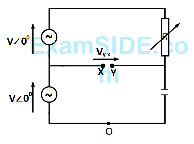
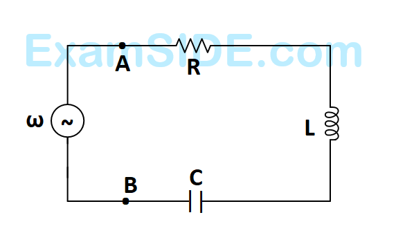
The phasor diagram which is applicable to this circuit is

GATE EE 2006
22
The $$RL$$ circuit of the figure is fed from a constant magnitude, variable frequency sinusoidal voltage source $${V_{IN.}}$$ At $$100Hz,$$ the $$R$$ and $$L$$ elements each have a voltage drop $${u_{RMS}}.$$ If the frequency of the source is changed to $$50Hz,$$ then new voltage drop across $$R$$ is GATE EE 2005 Electric Circuits - Sinusoidal Steady State Analysis Question 14 English
GATE EE 2005
23
In Fig. the admittance values of the elements in Siemens are
$${Y_R} = 0.5 + j0,$$
$${Y_L} = 0 - j\,1.5,$$
$${Y_C} = 0 + j\,0.3$$ respectively.
The value of $${\rm I}$$ as a phasor when the voltage $$E$$ across the elements is $$10\angle {0^0}\,V$$ is GATE EE 2004 Electric Circuits - Sinusoidal Steady State Analysis Question 15 English
GATE EE 2004
24
In the circuit of Fig. the magnitudes of $${V_L}$$ and $${V_C}$$ are twice that of $${V_R}$$. The inductance of the coil is GATE EE 2003 Electric Circuits - Sinusoidal Steady State Analysis Question 16 English
GATE EE 2003
25
In the circuit shown in Fig. what value of $$C$$ will cause a unity power factor at the $$ac$$ source? GATE EE 2002 Electric Circuits - Sinusoidal Steady State Analysis Question 20 English
GATE EE 2002
26
A series $$R-L-C$$ circuit has $$R = 50\Omega ;$$ $$L=100$$ $$\mu H$$ and $$C = 1\,\,\mu F.$$ The lower half power frequency of the circuit is
GATE EE 2002
27
In the circuit shown in Fig. it is found that the input $$ac$$ voltage $$\left( {{V_i}} \right)$$ and current $$i$$ are in phase. The coupling coefficient is $$K = {M \over {\sqrt {{L_1}{L_2}} }},$$ where $$M$$ is the mutual inductance between the two coils. The value of $$K$$ and the dot polarity of the coil $$P-Q$$ are GATE EE 2002 Electric Circuits - Sinusoidal Steady State Analysis Question 17 English
GATE EE 2002
28
A first order, low pass filter is given with $$R = 50\,\,\Omega $$ and $$C$$ $$ = 5\mu F.$$ What is the frequency at which the gain of the voltage transfer function of the filter is $$0.25?$$
GATE EE 2002
29
If an $$ac$$ voltage wave is corrupted with an arbitrary number of harmonics, then the overall voltage waveform differs from its fundamental frequency component in terms of
GATE EE 2000
30
The impedance seen by the source in the circuit in Fig. is given by GATE EE 2000 Electric Circuits - Sinusoidal Steady State Analysis Question 22 English
GATE EE 2000
31
A fixed capacitor of reactance –$$j0.02$$ $$\Omega $$ is connected in parallel across a series combination of a fixed inductor of reactance $$j0.01$$ $$\Omega $$ and a variable resistance $$R.$$ As $$R$$ is varied from zero to infinity, the locus diagram of the admittance of this $$L-C-R$$ circuit will be
GATE EE 1999
32
The voltage phasor of a circuit is $$10\angle {15^0}\,V$$ and the current phasor is $$2\,\,\angle - {45^0}A.$$ The active and the reactive powers in the circuit are
GATE EE 1999
33
Two identical coils of negligible resistance when connected in series across a $$200V,$$ $$50$$ $$Hz$$ source draws, a current of $$10$$ $$A.$$ When the terminals of one of the coils are reversed, then current drawn is $$8$$ $$A.$$ The coefficient of coupling between the two coils is
GATE EE 1997
34
A coil (which can be modeled as a series $$RL$$ circuit) has been designed for high $$-$$ $$Q$$ performance at a rated voltage and a specified frequency. If the frequency of operation is doubled, and the coil is operated at the same rated voltage, then the $$Q$$$$-$$factor and the active power $$P$$ consumed by the coil will be affected as follows
GATE EE 1996
35
In the given circuit, the voltage $$\overline {{V_L}} $$ has a phase angle of ____________ with respect to $$\overline {{V_S}} .$$ GATE EE 1994 Electric Circuits - Sinusoidal Steady State Analysis Question 13 English
GATE EE 1994

Marks 5

EXAM MAP
Medical
NEETAIIMS
Graduate Aptitude Test in Engineering
GATE CSEGATE ECEGATE EEGATE MEGATE CEGATE PIGATE IN
Civil Services
UPSC Civil Service
Defence
NDA
Staff Selection Commission
SSC CGL Tier I
CBSE
Class 12