Network Theorems · Electric Circuits · GATE EE
Marks 1
For the circuit shown, which one of the following options correctly identifies the Thevenin's equivalent parameters between nodes Y and Z ?

All the elements in the circuit are ideal. The power delivered by the 10 V source in watts is

For the circuit shown in the figure, $$V_1=8$$ V, DC and $$I_1=8$$ A, DC. The voltage $$V_{ab}$$ in Volts is __________ (Round off to 1 decimal place).

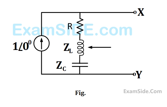
In the given circuit, for maximum power to be delivered to RL, its value should be ______ Ω. (Round off to 2 decimal places.)

The Thevenin equivalent voltage, Vth, in V (rounded off to 2 decimal places) of the network shown below, is ________


Marks 2
The terminal voltage and current of a linear electrical network shown in Figure (a) are given in the table.
$$ \begin{array}{|c|c|} \hline \text { Terminal voltage }\left(v_t\right) & \text { Terminal current }\left(i_t\right) \\ \hline 18 \mathrm{~V} & -0.5 \mathrm{~A} \\ \hline 30 \mathrm{~V} & 0.5 \mathrm{~A} \\ \hline 36 \mathrm{~V} & 1.0 \mathrm{~A} \\ \hline \end{array} $$

The correct choice for the parameters ( $\mathrm{I}_{\mathrm{N}}, \mathrm{R}_{\mathrm{N}}$ ) of the Norton equivalent circuit shown in Figure (b) is:
Consider the two-port network shown. For maximum power transfer to the resistive load $\left(R_L\right)$, the value of $R_L$ should be $\_\_\_\_$ $\Omega$. (Round off to two decimal places)

For the circuit shown, if $$i = \sin 1000t$$, the instantaneous value of the Thevenin's equivalent voltage (in Volts) across the terminals a-b at time t = 5 ms is __________ (Round off to 2 decimal places).

For the network shown, the equivalent Thevenin voltage and Thevenin impedance as seen across terminals 'ab' is

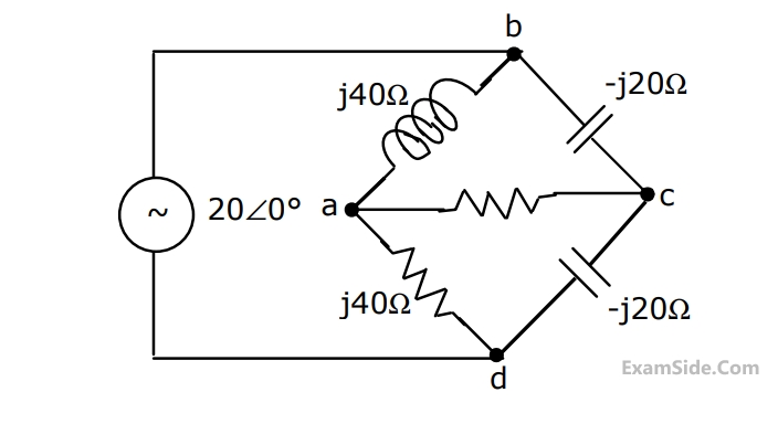
The current I flowing in the circuit shown below in Amperes is ________.


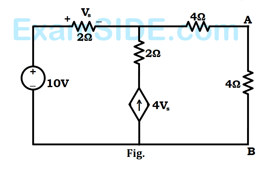
For the circuit given above, the Thevenin's resistance across the terminals $$A$$ and $$B$$ is
For the circuit given above, the Thevenin's voltage across the terminals $$A$$ and $$B$$ is


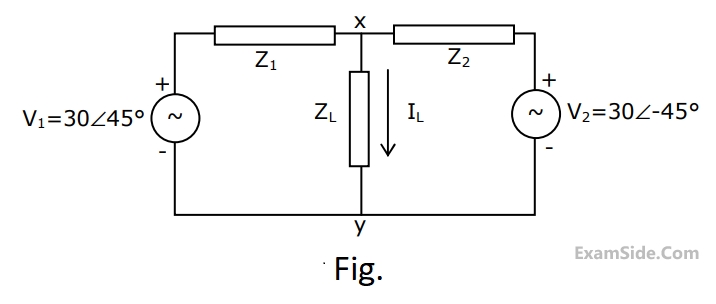
Marks 5
$${Z_1} = \left( {1 - j} \right)\Omega ,\,\,{Z_2} = \left( {1 + j} \right)\Omega $$ and $${Z_L} = \left( {1 + j0} \right)\Omega .$$ Obtain the Thevenin equivalent circuit (Thevenin voltage and impedance) across terminals $$X$$ and $$Y$$, and determine the current $${{\rm I}_L}$$ through the load $${Z_L}.$$