Load Flow Studies · Power System Analysis · GATE EE
Marks 1
Consider a power system with $N$ buses, of which $P$ are generator buses and the remaining $Q$ are load buses (where there is no generation).
Assume that there are no reactive power-limit violations at the generator buses. What is the size of the Jacobian matrix in the Newton-Raphson load flow method?
During a power failure, a domestic household uninterruptible power supply (UPS) supplies AC power to a limited number of lights and fans in various rooms. As per a NewtonRaphson load-flow formulation, the UPS would be represented as a
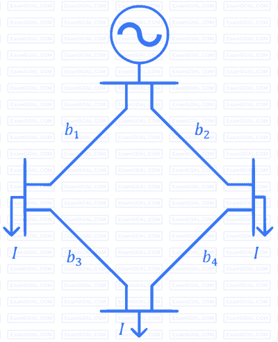
The figure shows the single line diagram of a 4-bus power network. Branches $b_1$, $b_2$, $b_3$, and $b_4$ have impedances $4z$, $z$, $2z$, and $4z$ per-unit (pu), respectively, where $z = r + jx$, with $r > 0$ and $x > 0$. The current drawn from each load bus (marked as arrows) is equal to $I$ pu, where $I \neq 0$. If the network is to operate with minimum loss, the branch that should be opened is
Consider a power system consisting of $N$ number of buses. Buses in this power system are categorized into slack bus. $P V$ buses and $P Q$ buses for load flow study. The number of $P Q$ buses is $N_L$. The balanced Newton-Raphson method is used to carry out load flow study in polar form $H, S, M$ and $R$ are sub-matrices of the Jacobian matrix $J$ as shown below:
$$ \left[\begin{array}{l} \Delta P \\ \Delta Q \end{array}\right]=J\left[\begin{array}{l} \Delta \delta \\ \Delta \gamma \end{array}\right] \text {, where } J=\left[\begin{array}{ll} H & S \\ M & R \end{array}\right] $$
The dimension of the sub matrix $M$ is
For the given circuit, $${Y_{bus}}$$ and $${Z_{bus}}$$ are bus admittance matrix and bus impedance matrix, respectively, each of size $$2\, \times \,2$$. Which one of the following statements is true?
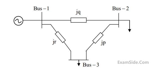
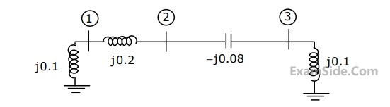
The per unit values of the line reactance's $$p, q$$ and $$r$$ shown in the figure are
$$\left[ {\matrix{ { - j6} & {j3} & {j4} \cr {j3} & { - j7} & {j5} \cr {j4} & {j5} & { - j8} \cr } } \right]\,pu$$
If the shunt capacitance of all transmission lines is $$50$$% compensated, the imaginary part of the $$3$$rd row $$3$$rd column element (in $$pu$$) of the bus admittance matrix after compensation is
$$y = j\left[ {\matrix{ { - 13} & {10} & 5 \cr {10} & { - 18} & {10} \cr 5 & {10} & { - 13} \cr } } \right]$$
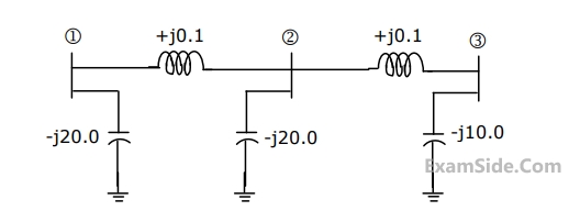
If each transmission line between the two buses is represented by an equivalent $$\pi \,$$ network, the magnitude of the shunt susceptance of the line connecting bus $$1$$ and $$2$$ is
Marks 2
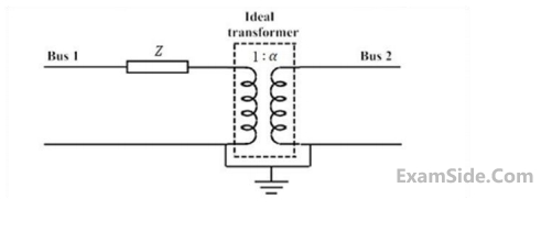
 The $Y$ bus representation of this transformation is
For the three-bus lossless power network shown in the figure, the voltage magnitudes at all the buses are equal to 1 per unit (pu), and the differences of the voltage phase angles are very small. The line reactances are marked in the figure, where $\alpha$, $\beta$, $\gamma$, and $x$ are strictly positive. The bus injections $P_1$ and $P_2$ are in pu. If $P_1 = mP_2$, where $m > 0$, and the real power flow from bus 1 to bus 2 is 0 pu, then which one of the following options is correct?

A 3-bus network is shown. Consider generators as ideal voltage sources. If rows 1,2 and 3 of the $Y_{h s}$ matrix correspond to bus 1,2 and 3 respectively, then $Y_{h s}$ of the network is

There is a transmission line connected between buses $$1$$ and $$3,$$ which is represented by the circuit shown in figure.
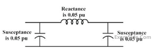
If this transmission line is removed from service what is the modified bus admittance matrix?
Assertion (A): Fast decoupled load flow method gives approximate load flow solution because it uses several assumptions.
Reason (R): Accuracy depends on the power mismatch vector tolerance.
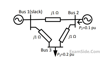
If the base impedance and the line-to-line base voltage are $$100\Omega $$ and $$\,100kV,\,\,$$ respectively, then the real power in MW delivered by the generator connected at the slack bus is
The voltage phase angles in rad at buses $$2$$ and $$3$$ are
The bus admittance matrix, $$Y$$-$$bus,$$ of the network is
The pre-fault voltages are $$1.0$$ $$p.u.$$ at all the buses. The system was unloaded prior to the fault. A solid $$3$$ phase fault takes place at bus $$2.$$
The per unit fault feeds from generators connected to buses $$1$$ and $$2$$ respectively are
The pre-fault voltages are $$1.0$$ $$p.u.$$ at all the buses. The system was unloaded prior to the fault. A solid $$3$$ phase fault takes place at bus $$2.$$
The post fault voltages at buses $$1$$ and $$3$$ in per unit respectively are
A branch having an impedance of $$j0.2\Omega $$ is connected between bus $$2$$ and the reference. Then the values of $${Z_{22,new}}$$ and $${Z_{23,new}}$$ of the bus impedance matrix of the modified network are respectively

Marks 5
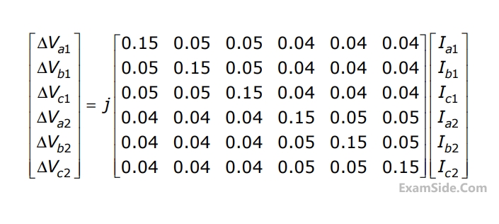
Compute the self and mutual zero sequence impedances of this system i.e, compute $${Z_{011}},\,\,{Z_{012}},\,\,{Z_{021}},\,\,{Z_{022}}\,\,\,$$ in the following equations.
$$\Delta {V_{01}} = {Z_{011}}\,{{\rm I}_{01}} + {Z_{012}}\,{{\rm I}_{02}}$$
$$\Delta {V_{02}} = {Z_{021}}\,{{\rm I}_{01}} + {Z_{022}}\,{{\rm I}_{02}}\,\,$$ where $$\,\Delta {V_{01}},$$
$$\Delta {V_{02}},\,{{\rm I}_{01}},\,{{\rm I}_{02}}\,\,$$ are the zero sequence voltage drops and currents for the two lines respectively.