Combinational Circuits · Digital Electronics · GATE EE

Start Practice

Marks 1

Marks 2

1
A Boolean function $$f\left( {A,B,C,D} \right) = \Pi \left( {1,5,12,15} \right)$$ is to be implemented using an $$8 \times 1$$ multiplexer ($$A$$ is $$MSB$$). The inputs $$ABC$$ are connected to the select inputs $${S_2}{S_1}{S_0}$$ of the multiplexer respectively. GATE EE 2015 Set 2 Digital Electronics - Combinational Circuits Question 6 English

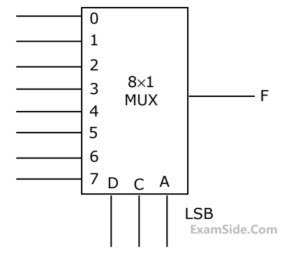
Which one of the following options gives the correct inputs to pins $$0,1,2,3,4,5,6,7$$ in order?

GATE EE 2015 Set 2
2
A $$3$$-bit gray counter is used to control the output of the multiplexer as shown in the figure. The initial state of the counter is $${000_2}.$$ The output is pulled high. The output of the circuit follows the sequence GATE EE 2014 Set 3 Digital Electronics - Combinational Circuits Question 7 English
GATE EE 2014 Set 3
3
Two monoshot multivibrators, one positive edge triggered $$\left( {{M_1}} \right)$$ and another negative edge triggered $$\left( {{M_2}} \right)$$ are connected as shown in figure. GATE EE 2014 Set 3 Digital Electronics - Combinational Circuits Question 8 English

The monoshots $${{M_1}}$$ and $${{M_2}}$$ when triggered produce pulses of width $${{T_1}}$$ and $${{T_2}}$$ respectively, where $${T_1} > {T_2}.$$ The steady state output voltage $${V_0}$$ of the circuit is

GATE EE 2014 Set 3
4
A $$3$$ line to $$8$$ line decoder, with active low outputs, is used to implement a $$3$$- variable Boolean function as shown in the figure: The simplified form of Boolean function $$F(X,Y,Z)$$ implemented in 'Product of Sum' form will be GATE EE 2008 Digital Electronics - Combinational Circuits Question 2 English
GATE EE 2008
5
A $$4 \times 1\,\,MUX$$ is used to implement a $$3$$- input Boolean function as shown in figure. The Boolean function $$F\left( {A,\,\,B,\,\,C} \right)$$ implemented is GATE EE 2006 Digital Electronics - Combinational Circuits Question 3 English
GATE EE 2006
6
The minimal product-of-sums function described by the $$K$$-map given in Fig. GATE EE 2000 Digital Electronics - Combinational Circuits Question 9 English
GATE EE 2000
7
The logic function $$F = AC + ABD + ACD$$ is to be realized using an $$8$$ to $$1$$ multiplexer shown in figure, using $$A, C$$ and $$D$$ as control inputs. GATE EE 1999 Digital Electronics - Combinational Circuits Question 10 English

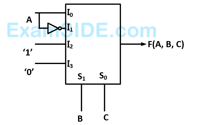
$$(a)$$ Indicate the inputs to be applied at the terminals $$0$$ to $$7.$$
$$(b)$$ Can the function be realize using a $$4$$ to $$1$$ multiplexer?
State YES or NO.

GATE EE 1999
8
Match the following GATE EE 1998 Digital Electronics - Combinational Circuits Question 11 English
GATE EE 1998

Marks 5

EXAM MAP
Medical
NEETAIIMS
Graduate Aptitude Test in Engineering
GATE CSEGATE ECEGATE EEGATE MEGATE CEGATE PIGATE IN
Civil Services
UPSC Civil Service
Defence
NDA
Staff Selection Commission
SSC CGL Tier I
CBSE
Class 12